
Related Manuals for Ceyear 6481 Series

Summary of Contents for Ceyear 6481 Series
- Page 1 6481 Series Optical Fiber Fusion Splicer Maintenance Manual China Electronics Technology Instruments Co., Ltd...
-
Page 2: Table Of Contents
Table of Contents 1 Product Introduction ..........................1 2 Functional Block Diagram ........................... 1 3 Common Fault ............................2 3.1 Common Faults of Instrument ......................2 3.2 Causes of Fusion Loss Increase and Solutions ..................3 4 Repair of Parts ............................4 4.1 Disassembly ............................ -
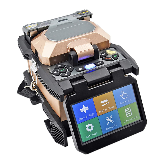
Page 3: Product Introduction
1 Product Introduction This manual applies to the repair of fiber fusion splicer 6481. The fiber fusion splicer is mainly used for the permanent connection of fiber and is widely used in the production test of fiber communication engineering and optical passive devices. This product is applicable for connecting the single-mode, multi-mode, non-zero dispersion, dispersion displacement and bending insensitivity and other quartz fibers with a cladding diameter of 80μm ~ 150μm. -
Page 4: Common Fault
Fig.2 Block diagram of whole machine 3 Common Fault 3.1 Common Faults of Instrument Table 1 Common faults of Instrument Phenomenon Cause Repair method 1. Damage of battery or adapter 1. Replace the battery or adapter 2. Power board cable not plugged 2. -
Page 5: Causes Of Fusion Loss Increase And Solutions
X/Y camera too bright or too Incorrect setting of CMOS gain Reset the gain value dark 1. Camera plate cable 1. Plug camera plate plugged cable Abnormal display of X/Y camera 2. Damage of camera plate or 2. Replace the camera plate or control board control board 1. -
Page 6: Repair Of Parts
Table 2 Causes of Fusion Loss Increase and Solutions Phenomenon Cause Solution Axial misalignment of fiber core Dirty V-groove or fiber presser Clean V-groove and fiber presser Improper discharge current Too fine Discharge Correction intensity Correct the propelling distance or Too short propelling distance increase the size of overlap Check whether the fusion mode is... -
Page 7: Propel Motor
Fig.3 Overall appearance of instrument 4.2 Propel Motor If “Left/right motor error” is displayed at the lower left corner of screen during the startup (as shown in Fig.4), the propel motor may be stuck. In most cases, the jam of motor is caused by the foreign objects between two gears of propel motor which may lead to the starting or propulsion failure. - Page 8 Fig. 4 Jam of propel motor...
- Page 9 Dust accumulates between gears, sometimes the foreign objects such as the exterior protection cover is stuck. The dust on the fitting part between the propel threaded rod and screw sleeve results in the stagnation Fig.5 Cleaning of foreign objects between motor gears...
-
Page 10: Align Motor
Screw of propel motor Screw of propel motor Screw of propel motor Fig. 6 Positions of propel motor screws 4.3 Align Motor In case of the displace motor error during the normal use or the align motor error during the self-test (as shown in Fig.7), the align motor has failed. - Page 11 Screws of align motor Fig.8 Align motor...
-
Page 12: Imaging Lamp
Align micrometer head Fig.9 Align micrometer head 4.4 Imaging Lamp White screen, sometimes with the discharge, occurs at the startup, or the instrument restarts when the windshield is opened or closed, or X/Y camera looks like black screen after the windshield is closed, it may be that the imaging lamp cable is damaged at the spindle or the imaging lamp cable is broken at the weld point of printed board, the imaging lamp and spindle shall be replaced. - Page 13 ⑤ Replace it with new imaging lamp, screw down 4 screws fixing the imaging lamp, insert the imaging lamp cable into two heat-shrink tube, and fit the imaging lamp cable into the spindle. ⑥ The heat-shrink tube on the heat-shrink imaging lamp cable is as shown in Fig.14. ⑦...
- Page 14 Screws fixing the imaging lamp Weld point may be broken Cable at spindle may be damaged Fig.11 Imaging lamp...
- Page 15 X26 cable is black, red, white blue sequence from inside to the outside Jet out the pin of X26 cable out of plug and do not discard the plug Fig.12 X26 cable...
- Page 16 Fig.13 Replacement of spindle...
-
Page 17: Heater
cable through here Fig.14 Installation of imaging lamp 4.5 Heater If the heater does not work or can not automatically heat (automatic heating function is on in the menu), first check whether cables X11 and X12 of control board are plugged in. If they are plugged in, it means that the heater is damaged and shall be replaced. -
Page 18: Power Board
Fixing screws of heater Fig.15 Heater 4.6 Power Board In case of the failure to start, charge or the flashing of charge indicator, the power board may be damaged. If the instrument fails to start, first check whether the cables of control board X1 and power board X3 are plugged in. -
Page 19: High-Voltage Board
X2 cable Fig.16 Removal of base Back power board R9 Power board X3 Fig.17 Power board 4.7 High-voltage Board In case of no discharge, check whether the connecting cables between the high-voltage board X1 and the control board X7 and between the high-voltage board X2 and the control board X6 is off or loose. Make sure that the connection is normal. -
Page 20: Control Board
High-voltage wire Fig.17 High-voltage board 4.8. Control Board In case of starting failure, check whether the control board FPGA load indicator V17 (as shown in Fig.18) is on. If not, the control board is damaged. Pull out all the cables on the control board, and remove the stopper fixing the control board (as shown in Fig.19) by extracting the control board if necessary. - Page 21 FPGA load indicator V17 X4 socket Fig.18 Main control panel...
-
Page 22: Light Path
X26 cable X4 socket Stopper fixing control board Fig.19 Stopper of main control panel 4.9 Light Path In case of the significant inclination of fiber image in X/Y camera, the position of CMOS camera plate of X/Y camera may be slightly changed due to the long-term vibration or self-stress. To rectify the fault, unscrew the screws on the camera plate of X/Y camera (as shown in Fig.20), manually adjust the position of camera plate of this image and observe the fiber imaging condition in the horizontal double-vision video of X/Y camera, and fix the screws when the image is centered and flush with another... -
Page 23: Repair And Calibration Of Instrument
Screws camera plate Fig.20 Camera plate 5 Repair and calibration of Instrument 5.1 Software Upgrade Fusion splicer comes with the system upgrade function, and the operating steps are as follows: In the power-off state, first hold on , and then click , the instrument will enter the upgrade state in about 2s (as shown in Fig.21). -
Page 24: Cleaning Of V-Groove
If the upgrade is abnormal, upgrade it again. Fig.21 Software upgrade interface 5.2 Cleaning of V-groove In case of the contaminant in V-groove, the fiber may not be properly clamped, which will cause the larger fusion losses. Therefore, V-groove shall be checked and cleaned regularly during the normal work process. -
Page 25: Cleaning And Replacement Of Electrode
Fig.22 Cleaning of V-groove Fig.23 Cleaning of presser 5.3 Cleaning and Replacement of Electrode If the electrode is dirty, clean the electrode with the Electrode Cleaning function of instrument maintenance in the main menu, and then wipe the tip of electrode gently with a cotton swab moistened with alcohol, or gently rub the tip of electrode with a 3mm wide and 50mm long metallographic sandpaper strip. -
Page 26: Adjustment Of Electrode Holder
a) Electrode shall be replaced when the instrument is shutdown. In case of the discharge, the high voltage up to thousands of volts on the electrodes will cause great harm to the human body. b) Open the windshield to present the electrode as shown in Fig.24; c) First loosen the screws of electrode cap, take off the electrode cap and take out the electrode. -
Page 27: Cleaning Of Objective Lens
b) After the above steps are completed, perform the discharge correction. 5.5 Cleaning of Objective Lens If the microscope objective lens is dirty, the normal observation of the fiber core position may be affected, which may lead to the higher fusion loss or poor connection. Therefore, both objective lenses shall be cleaned regularly. -
Page 28: Propelling Distance Test
multiple corrections are required to complete the process. The intermediate process does not require the re-preparation of fiber. 5.7 Propelling Distance Test Place the fiber with well-prepared cross-section into the fusion splicer, select the “Propelling Distance Test” item in the motor menu and press "Enter" button. Press this button again to start the propulsion test. The process is as follows: a)...
Need help?
Do you have a question about the 6481 Series and is the answer not in the manual?
Questions and answers