Table of Contents
Advertisement
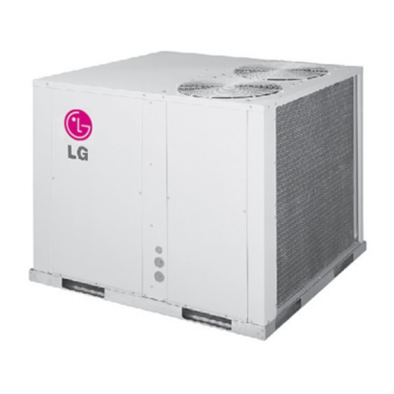
INSTALLATION MANUAL
AIR
CONDITIONER
Please read this installation manual completely before installing the product.
Installation work must be performed in accordance with the national wiring
standards by authorized personnel only.
Please retain this installation manual for future reference after reading it
thoroughly.
SINGLE PACKAGE TYPE AIR CONDITIONER
P/NO : MFL67445808
Copyright © 2014 - 2018 LG Electronics Inc. All Rights Reserved.
www.lg.com
Advertisement
Table of Contents

Related Manuals for LG AK-Q048GH50


Summary of Contents for LG AK-Q048GH50
- Page 1 Installation work must be performed in accordance with the national wiring standards by authorized personnel only. Please retain this installation manual for future reference after reading it thoroughly. SINGLE PACKAGE TYPE AIR CONDITIONER www.lg.com P/NO : MFL67445808 Copyright © 2014 - 2018 LG Electronics Inc. All Rights Reserved.
- Page 2 TIPS FOR SAVING ENERGY TIPS FOR SAVING ENERGY Here are some tips that will help you minimize the power consumption when you use the air conditioner. You can use your air conditioner more efficiently by referring to the instructions below: •...
-
Page 3: Important Safety Instructions
SAFETY PRECAUTIONS IMPORTANT SAFETY INSTRUCTIONS READ ALL INSTRUCTIONS BEFORE INSTALLING THE APPLIANCE. Always comply with the following precautions to avoid dangerous situations and ensure peak performance of your product WARNING It can result in serious injury or death when the directions are ignored CAUTION It can result in minor injury or product damage when the directions are ignored WARNING... - Page 4 SAFETY PRECAUTIONS • Be sure the installation area does not deteriorate with age. - If the base collapses, the air conditioner could fall with it, causing property damage, product failure, and personal injury. • Use a vacuum pump or Inert (nitrogen) gas when doing leakage test or air purge. Do not compress air or Oxygen and Do not use Flammable gases.
- Page 5 SAFETY PRECAUTIONS • Take care to ensure that nobody could step on or fall onto the unit. - This could result in personal injury and product damage. CAUTION Installation • Always check for gas (refrigerant) pressure after installation or repair of product. - Low refrigerant levels may cause failure of product.
-
Page 6: Table Of Contents
TABLE OF CONTENTS TABLE OF CONTENTS Group Control TIPS FOR SAVING Trial Run Mode ENERGY Self-Diagnosis Function IMPORTANT SAFETY Starting the Unit INSTRUCTIONS Final Installation Checklist and Maintenance INTRODUCTION Installation guide at the seaside Horizontal Features (3 / 4 / 5 RT) Down Flow Features (3 / 4 / 5 RT) DIMENSIONAL DATA (3 / 4 / 5 RT) -
Page 7: Introduction
INTRODUCTION INTRODUCTION Horizontal Features (3 / 4 / 5 RT) Front View Return Supply Motor access panel Rear View Air outlet vents Control access panel Drain hole Air intake vents Compressor access panel Other purpose hole Power wires hole Control wires hole... -
Page 8: Down Flow Features (3 / 4 / 5 Rt)
INTRODUCTION Down Flow Features (3 / 4 / 5 RT) Front View Motor access panel Bottom View Supply Return... - Page 9 INTRODUCTION Rear View Air outlet vents Control access panel Drain hole Air intake vents Compressor access panel Other purpose hole Power wires hole Control wires hole...
-
Page 10: Dimensional Data
DIMENSIONAL DATA (3 / 4 / 5 RT) DIMENSIONAL DATA (3 / 4 / 5 RT) Single packaged cooling Units are designed for outdoor mounting with vertical condenser discharge. They can be located either at ground level or on roof. Each unit contains an operating charge of Refrigerant as shipped. -
Page 11: Installation Of Unit
INSTALLATION OF UNIT INSTALLATION OF UNIT Inspection Recommended Lifting beam Rigging Method Check for damage after unit is unloaded. Report promptly, to the carrier, any dam- Spreader bar age found to unit. Do not drop unit. Check the unit nameplate to determine if the unit voltage is correct for the applica- tion. -
Page 12: Ductwork
INSTALLATION OF UNIT Slab Mount Ductwork "For ground level installation, the unit base Ductwork construction guidelines should be adequately supported and hold the unit near level. The installation must meet the Connections to the unit should be made with guidelines set forth in local codes." 76mm(3") canvas connectors to minimize noise and vibration transmission. -
Page 13: Condensate Drain Piping
INSTALLATION OF UNIT Condensate Drain Piping Please fix tightly using provided screw after placing remote controller setup board A 3/4 inch female condensate drain connec- on the place where you like to setup. tion is located on the corner of the unit next to - Please set it up not to bend because poor the motor access panel. - Page 14 INSTALLATION OF UNIT Please fix remote controller upper part into the setup board attached to the surface of the wall, as the picture below, and then, connect with setup board by pressing lower part. - Please connect not to make a gap at the remote controller and setup board’s upper and lower, right and left part.
- Page 15 INSTALLATION OF UNIT Please connect indoor unit and remote controller using connection cable. Please check if connector is normally connected. Product side Connecting cable <Meaning of wire color> Signal Yellow Black Please use extension cable if the distance between wired remote controller and the product is more than 10m(32.8ft).
- Page 16 INSTALLATION OF UNIT Wired remote controller installation - Since the room temperature sensor is in the remote controller, the remote controller box should be installed in a place away from direct sunlight, high humidity and direct supply of cold air to maintain proper space temperature.
-
Page 17: Electronic Wiring
INSTALLATION OF UNIT Electronic Wiring CAUTION Follow ordinance of your governmental organi- • Provide a circuit breaker between power zation for technical standard related to electri- source and the unit as shown below. cal equipment, wiring regulations and guid- ance of each electric power company. WARNING Main power source •... -
Page 18: Field Wiring
INSTALLATION OF UNIT Field Wiring 3 / 4 / 5 RT – 220 V ~ 50 Hz 1 Phase 2 Wires 50/60 Hz 220 V (Main Switch) Switch ELCB Power Line (2 Wires Cable) CAUTION • Unit ground Lines are required for preventing electrical shock accident during current leak- age, Communication disorder by noise effect and motor current leakage (without connection to pipe). -
Page 19: Connect The Cable To The Product
INSTALLATION OF UNIT Connect the cable to the Product Remove the cover control from the unit by loosening the screw. Connect the wires to the terminals on the control board individually as the following. Secure the cable onto the control board with the holder (clamper). Refix the cover control to the original position with the screw. - Page 20 INSTALLATION OF UNIT Conduit panel Conduit panel Lock nut Lock nut Conduit Conduit WARNING • Ground Lines to the product are required for preventing electrical shock accident during current leakage, Transmission disorder by noise effect and motor current leakage (without connection to pipe). CAUTION •...
-
Page 21: Dip Switch Setting In Indoor Main Pcb
INSTALLATION OF UNIT Dip Switch Setting in Indoor Main PCB Function Description Setting "Off" Setting "On" Default Selection of Master or Group Control Master Slave Slave Selection of Dry Contact Dry Contact Mode Variable Auto Mode Return Air Sensor Installed Sensor or Not Not installed Installed Installed CTI or not... -
Page 22: Trial Run Mode
INSTALLATION OF UNIT Trial Run Mode After installing the product, you must run a Test Run mode. For details related to this operation, refer to the product manual. -
Page 23: Self-Diagnosis Function
INSTALLATION OF UNIT Self-Diagnosis Function Error Indicator (Indoor) Error Indicator - The function is to self-diagnoisis airconditioner and express the troubles identifically if there is any trouble. - If more than two troubles occur simultaneously, primarily the lowest trouble fo error code is expressed. - Page 24 INSTALLATION OF UNIT Error Indicator (Outdoor) 2 Times 2 Times 2 Times LED01G (RED) 1 Sec. 1 Sec. 1 Sec. 1 Time 1 Time 1 Time LED02G (GREEN) 2 Sec. 2 Sec. Outdoor Error Ex) Error 21 (DC Peack) 3 / 4 / 5 RT Error LED 1 LED 2...
-
Page 25: Starting The Unit
INSTALLATION OF UNIT Starting the Unit Voltage With the compressor operating, check the line Heating Mode voltage at the unit. The voltage should be within the range shown on the unit name- (If unit is equipped with electric heater.) plate. If low voltage is encountered, check the Check to ensure all grilles and registers are size and length of the supply line from the open and all unit access doors are closed... -
Page 26: Final Installation Checklist And Maintenance
INSTALLATION OF UNIT Final Installation Checklist and Maintenance - Is the condenser fan and indoor blower operating correctly, with proper rotation and without undue noise? - Have voltage and running currents been checked to determine if it is within limits? - Have the air discharge grilles been adjusted to balance the system? - Has the ductwork been checked for air leaks and condensation? - Has the indoor airflow been checked and adjusted if necessary? - Page 27 INSTALLATION OF UNIT Maintenance Performed by Serviceman-Cooling Season To keep your unit operating safely and efficiently, the manufacturer recommends that a qualified serviceman check the entire system at least once each year, or more frequently if conditions warrant. Your serviceman may examine these areas of your unit: ‘...
-
Page 28: Installation Guide At The Seaside
Install the outdoor unit on - If you can’t meet above guide line in the the opposite side of the sea wind direction. seaside installation, please contact LG Electronics for the additional anticorro- sion. - Periodic ( more than once/year ) cleaning... - Page 29 LG Electronics México, S.A de C.V Sor Juana lnés de la Cruz No. 555 Col. San Lorenzo Industrial Tlalnepantla de Baz Estado de México C.P. 54033 Tel. 55 5321 1919 Página web http://www.lg.com.mx...
Need help?
Do you have a question about the AK-Q048GH50 and is the answer not in the manual?
Questions and answers