Advertisement
Quick Links
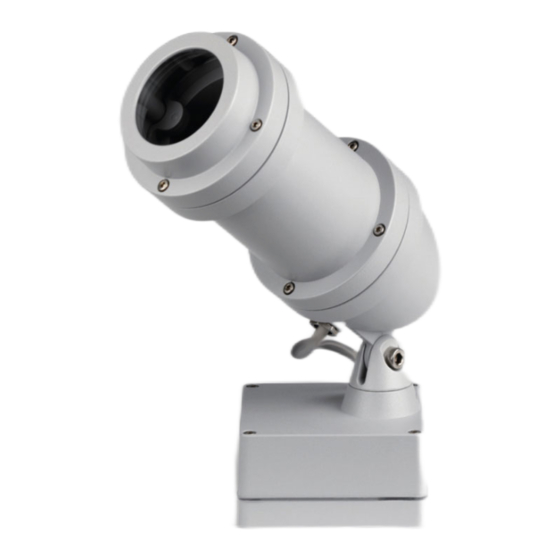
Anbauleuchte mit Hochleistungs-LED.
MONTAGEHINWEISE
Anschluß der Leuchte nach VDE 0100.
Anbauleuchte für ungeschützte Anlagen.
Leuchte ist geeignet für Montage auf
normal entflammbaren Baustoffen.
Achtung Hochspannung !
Vor dem Öffnen der Leuchte
oder Einsetzen des Gobos
Netzspannung trennen.
Schrauben an der Wanddose lösen und
Montageplatte entnehmen.
Montageplatte mit beiliegendem
Befestigungsmaterial anbringen.
Auf richtigen Sitz der elektrischen Zuleitung
in den Dichtungen achten.
Beim Aufsetzen der Leuchte auf die
Montageplatte elektrische Verbindung durch
Stecker herstellen.
Wanddose dicht verschrauben, dabei
Schrauben gleichmäßig über Kreuz anziehen.
Rahmenverlängerung
2
vom Gehäuse
3
nehmen.
Gobo und/oder Filter
4
in Gobohalterung
einlegen und ggfs. Ausrichten,
mit Gobofeder
6
fixieren.
Rahmenverlängerung
2
auf das Gehäuse
aufsetzen und dicht verschrauben, Schrauben
dabei über Kreuz gleichmäßig anziehen.
Zum Scharfstellen der Abbildung, Rahmen
mit Glas
1
von der Rahmenverlängerung
nehmen und mittels Kreuzschlitz-
Schraubendreher über Stellschraube
Objektiv in die gewünschte Position bringen.
Rahmen mit Glas auf Rahmenverlängerung
aufsetzen und dicht verschrauben, Schrauben
dabei über Kreuz gleichmäßig anziehen.
2
3
Nightspot A
LED Gobo
Anbauleuchte
Luminaire
Schutzart - Protection IP 65
Schutzklasse - Safety Class I
Luminaire with high performance LED.
MOUNTING INSTRUCTIONS
Connection of the light fitting in compliance
with the prevailing regulations in your
country. Luminaire for non protected outdoor
installation.
Luminaire is suitable for mounting on
normal inflammable surfaces.
Attention ! High Voltage !
Disconnect from power supply before
opening the light fitting or inserting the gobo.
Loosen the screws in the wall box and
remove the gear tray. Fix gear tray in place
using the fixing materials provided.
Ensure that the gasket forms a seal around
the power supply cable.
When placing the luminaire over the gear
tray, make electrical connection by plugging
the male and female parts of the connector
together. Tighten the screws in the wall box
cover crosswise.
Remove tubular extension
from the main housing .
Insert the Gobo or colour filter plus Gobo
5
into the Gobo Carrier
if necessary. Fix in place with Spring clip .
Put tubular extension
3
back onto housing
and tighten the screws.
To focus the image:
Remove front frame and glass
from the tubular extension and using
a cross slot (Philips) screwdriver,
7
das
adjust screw
7
until the correct position
is found (image is sharp).
Replace front frame and glass assembly
and screw down crosswise tightly.
1
6
8 975 0.5 010
8 975 0.6 010
2
3
4
5
and turn or adjust
6
2
3
1
5
4
.
Stemmessiepener Weg 5
D-58675 Hemer
7
1
Advertisement

Related Manuals for Meyer Gobo

Summary of Contents for Meyer Gobo
- Page 1 Attention ! High Voltage ! oder Einsetzen des Gobos Disconnect from power supply before Netzspannung trennen. opening the light fitting or inserting the gobo. Schrauben an der Wanddose lösen und Loosen the screws in the wall box and Montageplatte entnehmen.
- Page 2 In Strahlrichtung den Mindestabstand zu luminaire and illuminated surface is observed. angestrahlten Flächen einhalten ! min 0,2 m min 0,2 m Outer diameter of gobo : 37.5 mm Außendurchmesser Gobo : 37,5 mm Max. diameter of image : 25.0 mm max.
Need help?
Do you have a question about the Gobo and is the answer not in the manual?
Questions and answers