
Related Manuals for STARmed VIVA combo RF Generator


Summary of Contents for STARmed VIVA combo RF Generator
- Page 1 User’s Guide RF Lesion generator for tissue ablation during surgical procedures with Coagulation Electrode (ST-UM-15E Rev.9)
- Page 2 Only the certified medical doctors, capable of conducting surgical treatment using special techniques should use the described equipment in this user’s guide. The purpose of this user’s guide is to present the way to use the radiofrequency lesion generator and the electrode of STARmed. Caution This product can be sold only to the medical professional or based only on their request in accordance to the Medical Devices Law.
- Page 3 Product warranty Warranty is for one year. The company will repair this product for free during the warranty period, one year from the date of purchase, when there is malfunction or product defect that may have been a result of normal transportation and use. Repair is charged in the following cases.
-
Page 4: Safety Warning
Safety warning Danger Indication of the hazardous situation that could result in death, serious injury, or permanent impairment. Warning Indication of the hazardous situation that could result in minor or moderate harm to a body structure. Caution Precaution that describes an unsafe situation that could cause equipment damage or product malfunction. -
Page 5: Table Of Contents
Product warranty .................................. iii Safety warning ..................................iv System overview................................1 Caution for electric safety ............................2 Radiofrequency lesion generator ......................... 2 Peristaltic pump ................................2 Caution for general safety ............................3 Radiofrequency lesion generator with coagulation electrodes ............3 Grounding pads ................................ - Page 6 (5) Measuring Impedance ............................23 A. Operation and storage of PC linked monitor program ..............24 B. Installing and running of monitoring software on tablet PC (VIVALogger) ......29 C. Foot switch installation and operations guide ..................31 Labeling & Packaging ..............................34 Labeling ...................................
-
Page 7: System Overview
1. System overview Caution Use this equipment only after reading the warning, cautions and information on the product’s usage. Use other accessories related to this equipment only after reading the warnings, cautions, and information on the product’s usage. The user’s guide for the electrode is provided separately. -
Page 8: Caution For Electric Safety
Read the user’s guide before operating the RF Lesion generator and the pump. Caution User should not disassemble the equipment. Inquire with the STARmed on how to prevent electric shock. Disconnect the device from the power before cleaning or performing maintenance Electrical medical equipment requires special precautions regarding EMC. -
Page 9: Caution For General Safety
Caution for general safety VIVA combo RF Generator is radiofrequency generator for the cautery of tissue concerning the electrode’s tip due to the radiofrequency current. This equipment is safe from electric danger and it has obtained a permit based on the Medical Equipment Law. -
Page 10: Grounding Pads
Read the Instruction for Use (IFU) that is included with all electrodes from STARmed Co., Ltd for the correct grounding pad usage. The IFU includes the information on the preparation of the grounding pads, location for attachment, inspection, and removal. -
Page 11: Coagulation Electrode
Be careful not to overheat the grounding pads during ablation. Avoid air bubbles by carefully attach the grounding pads completely onto a patient. Remove body hair from the grounding pad area if necessary. To prevent the incident burn due to the contact between patient’s skin and skin, place gauze pad in the part where there is contact between the skin and skin in an appropriate manner. -
Page 12: Surgical Treatment Cautions
Please provide this user’s guide to operating and/or maintenance users. Important If the VIVA combo RF generator is affected by an electrostatic discharge(ESD) or power surge, the PC connection may get disconnected. If that happens, the PC linked program should be connected again. -
Page 13: Intended User Profile
Intended USER PROFILE Considerations Requirement description Minimum • Medical doctor who has medical license. Education Maximum • N/A • Knowledge of the side effect or complications due to the Minimum error of medical device. Knowledge • Clinical expertise with appropriate literature or training Maximum •... -
Page 14: System Description
RF generator with the PC via the communication cable. Applied part Grounding pads, Electrode tip Components VIVA combo RF Generator coagulation electrode set (optional: supplied separately) electrode conversion cable (optional) - Total Length : 0.28m±10, SPP Series Peristaltic pump foot switch (1 tier: blue) (optional): RF ON/OFF button function - Total Length : 4.1m±10, SN Series... -
Page 15: Emc Information
EMC Information Basic EMC Phenomenon standard or test Port tested Test level/requirement method Mains terminal CISPR11:2015 AC Mains Group2, Class A disturbance voltage Radiated disturbance CISPR11:2015 Enclosure Group2, Class A Harmonic Current Emission IEC 61000-3-2:2014 AC Mains Class A Pst: 1 Voltage change, Plt: 0.65 Voltage fluctuations and... -
Page 16: Preparations Before Use
Preparations before use Radiofrequency lesion generator 1. Check the rated voltage is correct for the equipment before connecting the power . Caution The equipment may be damaged if it is not connected to the correct voltage. 2. Warning: To avoid risk of electric shock, this equipment must only be connected to a power supply with protective earth. -
Page 17: Checking Rf Electrode And Tubing Set
Checking RF electrode and tubing set Connect the electrode and the tubing set in the following sequence: Note: Confirm that the power cables for the generator and the pump are connected. [VP01] 1. Place the IV bag above the patient and equipment to allow the air in the IV bag to elevate upward. - Page 18 7. Open the inflow tubing’s flip cover. Warning All RF electrodes from STARmed and tubing set are sterilized products for disposable use. Re-sterilization and reuse are prohibited. Stop using the electrode if the patient’s body temperature is not indicated on...
-
Page 19: Radiofrequency Lesion Generator
2. Radiofrequency lesion generator Caution Use the equipment only after reading the warnings, cautions, and information on the product’s usage. Use other accessories related to this equipment only after reading the warnings, cautions, and information on the product’s usage. The user’s guide for the electrode is provided separately. -
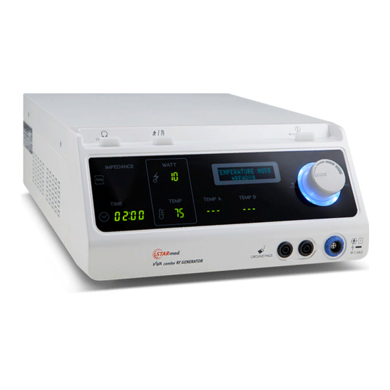
Page 20: Description Of Generator's Front Panel
Description of generator’s front panel Feature name Function OHM/RESET Measures the impedance of targeted tissue from the button active tip. Mode selected (General, Continuance, Auto, MODE button Temperature) button Indicates the menu setting concerning equipment operation, and indicated status including the power, Digital Display impedance, temperature, time.) at the time of operation. -
Page 21: Description Of Generator's Rear Panel
Description of generator’s rear panel Feature name Function Hole for cooling down the inside of the system Ventilation hole Foot switch Foot switch pedal connected with this part that offers connector the same function as that of the RF ON/OFF button (upper part) function Connecting part for the serial communication with PC,... -
Page 22: Description Of Generator's Side Panel
Description of generator’s side panel ③ ① ② Feature name Function Temperature Connector for temperature sensor to measure the sensor temperature of the target area. connector B Temperature Connector for temperature sensor to measure the sensor temperature of the target area. connector A Ventilation hole Hole for cooling down the inside of the system... -
Page 23: Main Screen
Main screen ① ③ ② ⑦ ④ ⑥ ⑤ Feature name Function Indicates the resistance value of the targeted tissue at IMPEDANCE the time of RF output. POWER- Indicates the actual amount of radiofrequency power that is supplied to the electrode and targeted tissue. MODE User setting mode is displayed Temperature measured at the temperature sensor... - Page 24 ⑧ Indicates message when the resistance value is too high or when the state of grounding pads, electrode System message 1 connection are faulty ⑨ Indicates message when RF output is 0 (General Mode System message 2 only). ⑩ Indicates message when the temperature is too high. System message 3 ⑪...
-
Page 25: Usage
Usage (1) AUTO Mode A) Check the digital display after selecting AUTO Mode by pressing MODE button. B) Turn the RF POWER Control Dial to set level of RF Power output. C) The level of RF POWER output can be set from 5W to 100W. D) The RF POWER output which user set up is generated with light up on RF START/STOP button if it is pressed. -
Page 26: General Mode
G) Button’s light is automatically off with stopping the RF POWER output after 12 minutes elapsed. H) Light of the RF START/STOP button will be turned off and the RF POWER output will be stopped by pressing RF START/STOP button even before the 12 minutes elapsed. -
Page 27: Continuance Mode(Track Ablation)
control dial while in use. Note: Maximum RF POWER output is 150W. E) RF POWER output, impedance, temperature of electrode and elapsed time will be displayed on VFD, FND screen. F) RF POWER output is stopped with light off when the RF POWER START/STOP button is pressed while in use. -
Page 28: Temperature Mode
control dial while in use D) RF POWER output, impedance, temperature of electrode and elapsed time will be displayed on VFD, FND screen. E) RF POWER output is stopped with light off when the RF POWER START/STOP button is pressed while in use. F) The RF POWER output is restarted from the RF POWER output value the most recently set up if RF START/STOP button is pressed again. -
Page 29: Measuring Impedance
E) RF POWER output is started with light up on RF START/STOP button if it is pressed. F) Temperature of procedure target is able to be monitored by temperature monitoring channel. Temperature sensor connector (5) Measuring Impedance A) Holding down OHM CHECK button to check impedance value displays on left side with light up on the button and if the button is released, it comes back to standby with light off Note : read the user’s guide for this equipment prior to the treatment and... -
Page 30: Operation And Storage Of Pc Linked Monitor Program
A. Operation and storage of PC linked monitor program Feature name Function Connect disconnect Serial Start monitoring communication between your PC and RF Generator. Path Select a folder which the log files will be saved to. To set an ID Auto/Manual Indicates the monitoring status of the output’s data Stop... - Page 31 1) Connect the generator to a computer that has the monitoring viewer program installed by using a cable that can carry out the USB communication. ☞ Caution: Connect the generator to the computer that has the software installed before running the software via USB communication cable. 2) Start the program by double clicking the ‘MRFALogger’...
- Page 32 Diagram 2 Diagram 3 ☞ Caution: USB communication may be disconnected depending on your PC. In that case, set the USB communication port again. 4) USB Serial Port Select and execute the port menu to set up the communication port that is currently in use.
- Page 33 In the “Serial port” drop-down box, select the USB serial port number in use for the viewer program. Press “OK” to connect the USB serial communication between the PC and RF Generator. Press the “Start Monitoring” button again to prepare for usage.
- Page 34 If the ID is set, the log file’s name will be extended with the ID. Each file name format is assigned below. - ‘ID_week_month_day_hour_minute_second_year_record.txt’ (example : STARmed_Fri_Jan_09_19H_14M_01S_2015_record.txt) 7) Display Configuration Set the Display Configuration to the desired display. (1) Generator Channel Type : - One Channel : The display for only one channel electrode generator.
-
Page 35: Installing And Running Of Monitoring Software On Tablet Pc (Vivalogger)
B. Installing and running of monitoring software on tablet PC (VIVALogger) 1) Installing APPLICATION (for Android only) Before install the APPLICATION on a tablet PC, make sure that third-party applications are allowed on the device. Go to Menu > Setting > Security > and check ‘Unknown Sources’... - Page 36 ⑤ Configuration - Setting Serial: Bluetooth setting ‘Scan for devices’ retrieves already discovered or known devices that are nearby. Select a Bluetooth device to connect to the tablet PC. Enter the correct code (Default paring code: 1234) and there will be a notification if the Bluetooth connection has successfully paired with the tablet - Write Info: Write information - About: Display version of VIVALogger...
-
Page 37: Foot Switch Installation And Operations Guide
C. Foot switch installation and operations guide ☞ Foot switch is an optional product accessory. Single Foot Switch Double Foot Switch Note : Connect the foot switch as the image above, then tighten the screws. User’s Guide for RF Lesion generator for tissue ablation during surgical procedures with coagulation Electrode (ST-UM-15E(Rev.9)) - Page 38 A) Single Foot Switch. The single foot switch pedal operates same function as the RF START/STOP button function. Note: Press the RF START/STOP button for more than 1 second to activate the RF output. The Single foot switch has the same function as the RF START/STOP Button User’s Guide for RF Lesion generator for tissue ablation during surgical procedures with coagulation Electrode (ST-UM-15E(Rev.9))
- Page 39 B) Double Foot Switch. The double foot switch pedals operate same function as the RF POWER control dial function Press the Yellow pedal to reduce RF POWER output by -5W. (Pressing and holding the pedal decreases RF POWER output quickly.) Press the Blue pedal to increase RF POWER output by +5W.
-
Page 40: Labeling & Packaging
Labeling & Packaging Labeling VIVA combo RF Generator (Box, product label) VIVA PUMP (Box, product label) VP01 ◼ VP01-1 ◼ Packaging Type of packaging : Corrugated cardboard box Mass of packaging : 1.5 kg User’s Guide for RF Lesion generator for tissue ablation during surgical procedures with coagulation Electrode (ST-UM-15E(Rev.9)) -
Page 41: Explanation Of Symbols
Explanation of symbols RF generator Symbol Meaning DEFIBRILLATION-PROOF TYPE BF APPLIED PART Floating return (high frequency) Warning, electricity General warning sign EC representative Footswitch input jack Signal input/output port Refer to instruction manual/booklet Equipotentiality Indicates rotational direction of increase (for output control and set output) RF START /STOP Non-ionizing electromagnetic radiation... -
Page 42: Box
Symbol Meaning To indicate that the transport package shall be kept away from rain and in dry conditions. To indicate that hooks shall not be used for handling the transport package. To indicate correct upright position of the transport package. To indicate that the contents of the transport package are fragile and the package shall be handled with care To indicate that the items shall not be vertically stacked... -
Page 43: Generator Output Power Characterization
Generator output power characterization (1) CONTINUANCE MODE (2) GENERAL MODE * For more information about the RF power, refer to the service manual User’s Guide for RF Lesion generator for tissue ablation during surgical procedures with coagulation Electrode (ST-UM-15E(Rev.9)) -
Page 44: Diagram Of Power Output Data
Diagram of power output data (1) 150W (maximum output current :2A) (2) 200W(maximum output current :2A) User’s Guide for RF Lesion generator for tissue ablation during surgical procedures with coagulation Electrode (ST-UM-15E(Rev.9)) -
Page 45: Radiofrequency Lesion Generator Specifications
Radiofrequency lesion generator specifications Rated power Voltage range: 100 - 240 V~ Maximum input power: 450 VA Fuse capacity: F5 AH 250V Power frequency: 50/60 Hz Impedance measurement Range: 10 - 800 ohms Resolution: 1 ohm 10 - 50 ohms ±10 ohm Accuracy: 51 - 300 ohms ±15% 301 - 800 ohms ±30%... -
Page 46: Peristaltic Pump
3. Peristaltic pump Caution Use this Peristaltic pump only after reading the warnings, cautions, and information on the product’s usage. Use other accessories related to the peristaltic pump only after reading the warnings, cautions, and information on the product’s usage. User’s Guide for RF Lesion generator for tissue ablation during surgical procedures with coagulation Electrode (ST-UM-15E(Rev.9)) -
Page 47: Description
Description ① ② ③ ④ VP01 Description of the pump front part and control part Feature name Function Handle Handle that use for moving of pump Switch that starts and stops the operation of the Power Switch pump roller Maintains proper contact status between the Tube compression pump tubing and roller... - Page 48 ① ② ③ Description of the pump’s rear part[VP01,VP01-1] Feature name Function MAINS INLET AC Power cable coupler FUSE box Two fuses attached Equipotential coupler for making the equipment EQUIPOTENTIAL besides the main frame and the electric potential, GROUND the same User’s Guide for RF Lesion generator for tissue ablation during surgical procedures with coagulation Electrode (ST-UM-15E(Rev.9))
-
Page 49: Preparations
Preparations Mounting the pump tubing inside of the front part(VP01) Lift up the cover by pushing the TUBE COMMPRESSION LEVER to the left. Mount the tubing to the inner side of the roller head. When mounting, mount the tubing by lifting up the TUBE AUTOMATIC CLAMP. -
Page 50: Peristaltic Pump Specifications
Peristaltic pump specifications Rated power Input voltage 100 - 240 V~ Frequency 50/60 Hz Consumption power 80 VA (max.) Flow rate (when using while connecting to the electrode tubing set) load = 80ml or higher Flow rate : (no load = 120 ml or higher) Dimension Size ( w x h x d ) 193 * 160 * 135 mm... -
Page 51: Others
4. Others Caution Use generator only after reading warning and caution messages and information on the usage first. Use other accessories related to this generator only after reading information on the usage, and warning and cautioning messages first. The guide related to electrode is provided separately. -
Page 52: Device Classification
Device Classification Classification as per EN 60601-1, the manufacturer describes the VIVA combo RF generator as: Type of protection against electric shock: class I Degree of protection against electric shock: Generator → Type BF Defibrillator Protected Pump → Not applicable Degree of harmful ingress of water: IPX 0 Mode of operation:... -
Page 53: Equipment Waste And Management
Equipment waste and management - Discard Please call or Consult your local STARmed representative for supporting. -This product can only be treated or disposed of in facilities with the appropriate authorisations (waste management licences / permits) - This product does not use of components and parts that contain stored energy or pose other HAZARDS that can result in an unacceptable RISK to disassemblers or others. -
Page 54: Maintenance And Service
The RF lesion generator and pump are not user serviceable, and both units should be returned to STARmed authorized service center if any problems arise. To ensure accuracy of unit outputs and displays, the annual inspection of the unit is recommended by official process. -
Page 55: Other Matters
Other matters A. Product name: Radiofrequency lesion generator (ClassIIb by CE classification) Brand name : VIVA combo RF Generator Model name: VCS10 B. Manufacturer’s business name: STARmed Co.,Ltd Manufacturer’s address: (Jungsan-dong, Daebang-Triplaon Business Tower), B-dong, 4F & 12F, 158, Haneulmaeul-ro, Ilsandong-gu, Goyang-si, Gyeonggi-do, Korea C.
Need help?
Do you have a question about the VIVA combo RF Generator and is the answer not in the manual?
Questions and answers