Table of Contents
Advertisement
Quick Links
Description :
FC 785-PC Fruit thermostat
Type:
MANUAL
File:
Do012063 FC785-PC v2.0
EN.wpd
Software:
MC785FC Version: V2.04
VDH Products BV - Roden - Holland
FC 785-PC
User manual
(Wall and panel mounting)
Number of pages:
By:
Signed:
Doc. nr.:
20
Version:
BJB
Date:
File:
012063
V2.0
29-04-2010
Doc 01
Advertisement
Table of Contents

Subscribe to Our Youtube Channel
Related Manuals for VDH FC 785-PC


Summary of Contents for VDH FC 785-PC
- Page 1 (Wall and panel mounting) Description : FC 785-PC Fruit thermostat Doc. nr.: 012063 Type: MANUAL Number of pages: Version: V2.0 File: Do012063 FC785-PC v2.0 Date: 29-04-2010 EN.wpd Software: MC785FC Version: V2.04 VDH Products BV - Roden - Holland Signed: File: Doc 01...
-
Page 2: Table Of Contents
1.1 FC 785-PC controller ........ -
Page 3: Technical Specifications
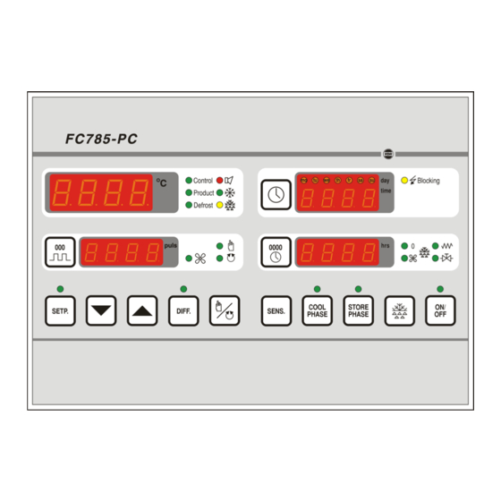
To enhance cooperation of multiple FC 785-PC controllers on one Alfanet RS485 Network, it is advised that the FC 785-PC controllers to apply must have the same software version numbers. Controllers with different software version numbers may not properly work together. - Page 4 User manual Document nr. : 012063 Version : V2.0 FC 785-PC Client : General Page : 4 of 20 Keys : ON/OFF = Controller ON/OFF key with LED SETP. = Set point push key with LED (UP) = Up key (increase value) ...
-
Page 5: Lms Relay (Extension) Module
User manual Document nr. : 012063 Version : V2.0 FC 785-PC Client : General Page : 5 of 20 1.2 LMS Relay (extension) module: (Max. 1 module) Supply : 12Vdc (100mA) (From separate supply) Communication C network (3-wire 0V,SDA,SCL) Address-jumpers : Place J1 and J2 always. -
Page 6: Functional Specifications
User manual Document nr. : 012063 Version : V2.0 FC 785-PC Client : General Page : 6 of 20 Functional specifications The FC-785 PC has three function-modes namely; 1. Standby-phase: The controller switches only on when hot-gas for another controller, to defrost, is needed. -
Page 7: Control
(LED is on). During electrical- or hot-gas-defrost the fan switches off. The LED’S next to the pulses-display shows the status of the fan. The LED is on if the fan is active. At power-up, the FC 785-PC fan-mode is set to automatic-mode (... -
Page 8: Setting Defrost Mode
User manual Document nr. : 012063 Version : V2.0 FC 785-PC Client : General Page : 8 of 20 3.7 Setting defrost mode. By pressing the key one ore more times the defrost-mode can be set, depending on parameter P 501 and P 502. The LED’s besides the running hour counter shows the defrost- mode which is used for controlling the defrost. -
Page 9: Programming Internal Settings
User manual Document nr. : 012063 Version : V2.0 FC 785-PC Client : General Page : 9 of 20 3. INFO menu During the info menu, the status of relay 1 .. 7 is indicated by the day LEDs mo .. su. -
Page 10: Parameter Table
User manual Document nr. : 012063 Version : V2.0 FC 785-PC Client : General Page : 10 of 20 4.1 Parameter table. Description Range Units Default Sensor function group: P 101 Function sensor-1 (FC785-PC Pt100-1) 0..7 0 = not present... - Page 11 User manual Document nr. : 012063 Version : V2.0 FC 785-PC Client : General Page : 11 of 20 Description Range Units Default Ventilation group: P 401 Ventilation delay after cooling switches off 0..99 minutes P 402 Automatic ventilation mode: 0..2...
- Page 12 User manual Document nr. : 012063 Version : V2.0 FC 785-PC Client : General Page : 12 of 20 Description Range Units Default Alarm group: P 601 Absolute minimum alarm during pre-cooling -40.0..50.0 °C P 602 Absolute minimum alarm delay during pre-cooling 0..99...
-
Page 13: Sensor Calibration
= Relative maximum temperature alarm Other alarms: = No hot-gas defrosting possible because there are no other FC 785-PC’s in the subnet. The alarm-reports will be visualized in the temperature display (upper left display). Alarm Reset: If a new alarm occurs, the alarm will be first continuously displayed in the display. -
Page 14: Front Views
User manual Document nr. : 012063 Version : V2.0 FC 785-PC Client : General Page : 14 of 20 Front views Front view FC 785 -PC wall mounting Front view FC785-PC panel mounting, drawing 100416... -
Page 15: Connections
User manual Document nr. : 012063 Version : V2.0 FC 785-PC Client : General Page : 15 of 20 Connections Connections FC 785-PC wall-mounting, drawing 992374w6... - Page 16 User manual Document nr. : 012063 Version : V2.0 FC 785-PC Client : General Page : 16 of 20 Connection diagram 992468w7: FC785-PC wall-mounting + LMS Relay module + LMS Pt100 module LMS Supply module...
- Page 17 User manual Document nr. : 012063 Version : V2.0 FC 785-PC Client : General Page : 17 of 20 Connections FC785-PC panel-mounting, drawing 992375w5...
- Page 18 User manual Document nr. : 012063 Version : V2.0 FC 785-PC Client : General Page : 18 of 20 Connections RS 485 Network: Connections RS485-network with network numbers and subnetwork numbers:...
-
Page 19: Dimensions
User manual Document nr. : 012063 Version : V2.0 FC 785-PC Client : General Page : 19 of 20 Dimensions Dimensions FC785-PC wall-mounting, drawing 940024 Dimensions FC785-PC panel-mounting, drawing 961271... - Page 20 User manual Document nr. : 012063 Version : V2.0 FC 785-PC Client : General Page : 20 of 20 Dimensions LMS Relay-module, drawing 970983 Dimensions LMS Supply-module and LMS Pt100-module, drawing 970908 -.-.-.-.-.-.-.-.-.-...
Need help?
Do you have a question about the FC 785-PC and is the answer not in the manual?
Questions and answers