
Related Manuals for REI HD Series


Summary of Contents for REI HD Series
- Page 1 SD-300 SD-300 HD Series 3 Channel Mobile Recorder Hardware User Manual Hardware Installation Manual Page 1 of 55 Radio Engineering Industries, Inc. 640548 – Rev A – 5/28/20...
-
Page 2: Table Of Contents
SD-300 Table of Contents List of Figures ........................ 4 Introduction ........................6 Features ......................... 6 System Overview ......................8 Front and Back Panels ....................9 Live View: ........................ 10 SD Card ........................11 SD Card Loading and Unloading ..................11 Record Time Estimator .................... - Page 3 SD-300 Export Configuration Menu ................39 Upgrade Firmware ..................39 Reset to Defaults .................... 39 Camera Names ....................40 USB Config Download Setup ................ 40 Input Setup ......................41 Speedometer Setup..................41 Input Setup ....................42 Network Setup ....................46 General Network Setup ..................
-
Page 4: List Of Figures
SD-300 List of Figures Figure 1: SD-300 Series System Diagram ................ 8 Figure 2: Front Panel Layout ................... 9 Figure 3: Rear Panel Layout ..................10 Figure 4: Estimator for Record Times ................13 Figure 5: Event Marker Button – Harness Connection ........... 15 Figure 6: GPS Antenna Module Harness Connection ............. - Page 5 SD-300 Figure 48: Accelerometer Set Up ................... 44 Figure 49: Accelerometer Sensitivity ................45 Figure 50: Accelerometer Threshold ................45 Figure 51: Network Set Up .................... 46 Figure 52: General Network Set Up ................46 Figure 53: Server Set Up ....................47 Figure 55: Wireless Network ..................
-
Page 6: Introduction
SD-300 Introduction All of us at REI would like to thank you for purchasing an SD-300 Mobile Recording System. This manual is intended to provide the user with the information required for proper installation, initial setup, and explanation of the individual programming options. - Page 7 SD-300 Image Viewing ● DVD-quality steaming ● Convenient USB media updating and status file downloading Retrieval and Archiving ● USB 3.0 (2.0 compatible) port on the front panel for easy image retrieval on the vehicle with a notebook computer or USB flash drives ●...
-
Page 8: System Overview
SD-300 System Overview Figure 1: SD-300 Series System Diagram Page 8 of 55 Radio Engineering Industries, Inc. 640548 – Rev A – 5/28/20... -
Page 9: Front And Back Panels
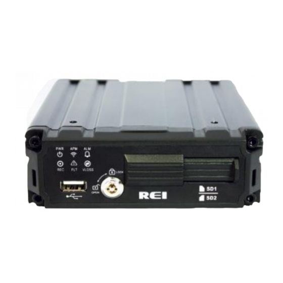
SD-300 Front and Back Panels Power Indicator Light Recording Indicator Light Wireless Access Point Active Light Fault Light Alarm Active Indicator Light USB 3.0 Port (2.0 capable) Image Loss Indicator Secure Faceplate Lock for SD Cards SD Card Slot 1 (512GB max) 10 SD Card Slot 2 (512GB max) Figure 2: Front Panel Layout Page 9 of 55... -
Page 10: Live View
SD-300 Network Port – IP Camera or 4G Modem 11 GPS Module Serial Port 12 AHD Camera Serial Port (Primary) WiFi Antenna Mini Coax Port Event Marker Port – 7 Sensors 13 AHD Camera Serial Port 14 Power Serial Adaptor Port Video Out for Live View Figure 3: Rear Panel Layout Live View:... -
Page 11: Sd Card
Menu Configuration section of this manual. When accessing the menu, it is necessary to connect a windows laptop (with REI VMS loaded on the laptop) to the network port of the unit (utilizing CAT5 cable and... - Page 12 SD-300 Loading SD Card: To install your SD cards, the SD cards will only easily insert into the SD Card Slots when faced the right direction. Slide the SD card into the slot until it clicks into place. Unloading SD Card: To remove SD card Simply press on the card and the card should partially eject from the slot.
-
Page 13: Record Time Estimator
SD-300 Record Time Estimator To help estimate record times please visit our website http://radioeng.info/rte/ Figure 4: Estimator for Record Times Long Term Storage Although the SD-300 Series Mobile Recorder system draws very little current in the stand-by mode, if the systems are installed but not used for an extended period of time (longer than 2 weeks) it is recommended that the power be disconnected from the Mobile Recorder to avoid draining the vehicle battery. -
Page 14: System Wiring - Power And Camera Cables
SD-300 System Wiring – Power and Camera Cables Note: All cables should be hidden from view. For the basic system there are five (5) cables, one (1) power cable (P/N 512929) 10 Feet, one (1) camera cable 10 Feet (P/N 512931 or any different length cable),One (1) record indicator / event mark button harness (P/N 530203) for external record indication and alarm/event marking, One (1) GPS harness (P/N 710745) used for satellite location and movement information, and one (1) vehicle... -
Page 15: Event Marker Button - Harness Connection
SD-300 Event Marker Button - Harness Connection Figure 5: Event Marker Button – Harness Connection The optional Digital SD-300 Series Event Marker Button (part# 530203) plugs into the connection labeled Event Marker (or Panic Button) on the SD-300 Vehicle Sensor Harness (part# 512934). -
Page 16: Gps Antenna Module Harness
SD-300 GPS Antenna Module Harness SD-300 710742 Figure 6: GPS Antenna Module Harness Connection The GPS antenna module harness (710745) plugs into the back of the SD-300 as shown above. This module will track up to twelve satellites at a time while providing one- second navigation updates at low power consumption. -
Page 17: Vehicle Sensor Harness
SD-300 Vehicle Sensor Harness Figure 7: Vehicle Sensor Harness Connection The SD-300 Vehicle Sensor Harness connects to various locations in the vehicle to provide on-screen information regarding vehicle performance. Vehicles have different sets of signals that can be monitored. Three levels of on-screen displays are available to the installer application: Taxi, Limousine, and Fleet. -
Page 18: Accelerometer Module Harness
SD-300 Taxi Meter FRONT DOOR OPEN REAR DOOR OPEN SPEEDOMETER XX MPH (SEE NOTE 1) NOTE: The XXs represent the vehicle speed (i.e. 35). Accelerometer Module Harness Figure 8: Accelerometer Module Harness Connection The optional external Accelerometer, or Inertia Sensor, must be hard mounted to the vehicle floor, frame, or some other non-dampened part of the vehicle (non-vibrating flat surface). -
Page 19: Physical Mounting Requirements
SD-300 Physical Mounting Requirements L Bracket Mounting Figure 10: L Bracket Mounting The SD-300 has two mounting brackets on the sides for easy mounting, as shown above. This type of installation is recommended for mounting behind the dash, in the trunk, or in a secure location in the vehicle. -
Page 20: Security Cover Mounting
SD-300 Security Cover Mounting There may be installations that require the back of the SD-300 get enclosed in its own protective enclosure. Security covers can be installed to protect the back connections on the SD-300. Figure 12: Security Cover Mounting IMPORTANT: Check local, state, and federal guidelines as to modification of the existing structures within the vehicle. -
Page 21: Camera Placement
SD-300 Camera Placement The SD-300 cameras can be mounted anywhere in the vehicle, as long as you have a stable mount that won’t vibrate excessively. The suggested mounting locations are to the right or just below of the rear-view mirror for the inward facing camera (710748 or 710751). -
Page 22: System Shut-Down
Play, Stop, Pause, Fast Forward, Fast Rewind, Slow Forward, Slow Rewind, Frame Forward, and Frame Reverse. SD Card Using the REI VMS PC Software, the user can access the files by connecting SD card to the computer directly PC Network Connection... - Page 23 SD-300 Username: admin Password: 11111111 In order to access the SD-300 from a computer, the TCP/IP network settings on the computer need to be set up accordingly to match the settings in the SD-300 to insure both devices are in the same network. IP Address: 192.168.0.x (x being any number but different from SD-300 IP address) Net Mask: 255.255.255.0 (Net Mask)
-
Page 24: Main Menu Page
Main Menu Page Figure 15: Main Menu SD-300 Main Menu can be accessed by using any standard USB mouse or REI offers a Handheld USB Trackball Mouse; part number 690896. Then the user can access recorded images and customize the settings on the SD-300. -
Page 25: Advanced Setup Menu
SD-300 Advanced Setup Menu This section describes where all of the various record configuration settings can be viewed or set using a video monitor and a USB mouse. Figure 16: Advanced Setup Menu The Setup section of the Menu is subdivided into four main categories: System Setup, Video Setup, Input Setup, Network. -
Page 26: Vehicle I.d. Menu
SD-300 Vehicle I.D. Menu Figure 18: Vehicle I.D. Vehicle I.D Menu allows the user to enter Vehicle I.D., Company name, Driver information, and an Installer ID. Vehicle I.D.: allows custom information to identify the SD-300s, such as medallion number. Company Name: allows the user to enter company name utilizing the SD-300 Driver: allows user to enter a driver’s name. -
Page 27: Figure 20: Custom Dst Triggers
SD-300 10-year internal battery backup for consistent and reliable time keeping over the life of the SD-300 system. Time/Date shows the current date and time, allowing the user to change the date and time. Display Format allows user to select between 12-hour or 24-hour display format. Sync Source allows the SD-300 to synchronize to a time synchronization service, either GPS (Global Positioning System), or NTP (Network Time Server), or None. -
Page 28: Operating Mode Menu
SD-300 Operating Mode Menu The Start Up Menu allows the user to choose when the SD-300 starts/stops recording, how long the SD-300 stays on after shutting off the ignition. Start Up Mode lets user to choose when the SD-300 starts recording. There are three settings for user to choose: Ignition, Schedule, Either Ignition or Schedule. -
Page 29: Figure 23: Ignition Or Schedule Start Up
SD-300 Figure 23: Ignition or Schedule Start Up Schedule section of the menu is where the user can set the date and times that the SD-300 will automatically turn on and shut off. Record Schedule: Mon, Tue, Wed, Thu, Fri, Sat, Sun. Options for schedule 1 and schedule 2, both have start and stop times. -
Page 30: Figure 25: Faults
SD-300 Figure 25: Faults Audio/Visual Setup menu allows SD-300 to display Audio/Visual alert if the SD- 300 is experiencing an alert condition. Fault Indicator: the types of alerts that the user can select for visual/audio alert. Blind Camera: Camera blocked by objects. Image Loss: not receiving camera images. -
Page 31: Password
SD-300 Standby Mode Display: allows SD-300 to display faults and alarms in standby mode. Display Faults: allows SD-300 to display faults in standby mode. Display Alarms: allows SD-300 to display alarms in standby mode. Standby Period: allows user to how many minutes for the standby period. Password Figure 26: Password The Password Menu gives user the ability to secure the SD-300 and it’s SD... - Page 32 SD-300 SD Card Password: password to access images directly from the SD memory card. For example; if the driver of the car was robbed or assaulted the police may want to pull the SD memory card(s) for evidence. Only an authorized agent will be able to access the images and audio on that card.
-
Page 33: Video Setup
SD-300 Video Setup Figure 27: Video Setup The Video Setup section of the menu is subdivided into seven main categories, Camera Setup, Alarm, SD, Sub-Stream, Image, Motion and OSD. Page 33 of 55 Radio Engineering Industries, Inc. 640548 – Rev A – 5/28/20... -
Page 34: Camera Setup
SD-300 Camera Setup Figure 28: Camera – Camera Setup The Camera Setup subsection of the Video Setup section allows the user to change all the related camera record settings, such as number of cameras, resolution, frame rate, etc. Custom Configuration: Custom record setting for each camera. Figure 29: Custom Record Settings Page 34 of 55 Radio Engineering Industries, Inc. - Page 35 SD-300 The Custom Record setting allows user to customize record setting to each individual camera. Channel: Enable channel to display on screen when selected. Note: When Live is selected but Rec is not selected, SD-300 only displays that camera image but does NOT record it. Res: Record resolution.
-
Page 36: Alarm
SD-300 Alarm Figure 30: Alarm Set Up Pre-Alarm images to include with Alarm: user can select between 0-300 seconds of record time. Post-Alarm images to Include with Alarm: user can select between 10- 1800 seconds of record time. SD Card Figure 31: SD Set Up SD Record Mode: Alarm or Mirror Alarm SD Record Mode: Records only during alarm to the SD... -
Page 37: Sub-Stream
SD-300 Mirror SD Record Mode: Mirrors the settings for the image recorded to the main hard drive. SD Record Stream: Main or Sub Main SD Record Stream: Primary stream that has a direct effect on your record quality. You can make changes to this under Camera section. -
Page 38: Image
SD-300 Image Figure 33: Image Set Up The user can customize all the settings for each camera individually. You can choose between four options: Brightness, Contrast, Color, and Saturation. Each having a range between 0 to 63. OSD (On Screen Display) Figure 34: OSD (On Screen Display) Set Up OSD: On Screen Display –... -
Page 39: Export Configuration Menu
SD-300 Export Configuration Menu Figure 35: Export Configuration Export Configuration Menu allows user to export current SD-300 settings onto an external storage for quick multiple SD-300 installation. Upgrade Firmware Figure 36: Upgrade Firmware Upgrade Firmware allows user to upgrade the SD-300’s Main and MCU firmware to the latest version. -
Page 40: Camera Names
SD-300 Camera Names Figure 38: Camera Names Camera Names Menu allows user to set camera name individually. Each camera name is displayed on the screen inside each window. Use on-screen keyboard to enter names. USB Config Download Setup Figure 39: Export and Import Configuration The Config tab under Maintenance is where you can import a certain configuration for a company or local mandated standard. -
Page 41: Input Setup
SD-300 Input Setup Figure 40: Input Set Up The Input Setup Menu contains all the settings to configure SD-300’s inputs including: Speed, Input, Accel, and GPS Port Setup. Speedometer Setup Figure 41: Speedometer Set Up Page 41 of 55 Radio Engineering Industries, Inc. 640548 –... -
Page 42: Input Setup
SD-300 Speedometer Setup Menu contains settings to change speedometer source, speed unit, speedometer calibration, and high-speed alarm. Speed Source: the source that the SD-300 is reading speed from GPS. Speed Unit: SD-300 supports MPH and KMH speed units. Overspeed Alarm: when select On, if speedometer reading is higher than threshold value, SD-300 records images as high-speed alarm for the duration that you set. -
Page 43: Figure 47: Input Set Up - Custom
SD-300 Figure 43: Input Set Up - Custom Input #: the input numbers correspond to pin number of the SD-300 input. Panic: name of the signal. PB: OSD abbreviation. Input When Activate: set to High if signal is high (positive) when activated; set to Low if signal is low (ground or negative) when activated. - Page 44 SD-300 Figure 44: Accelerometer Set Up The Accelerometer Setup Menu gives user options to configure accelerometer. Calibrate Accelerometer: accelerometer must be calibrated after installation. Select Calibrate to calibrate accelerometer. Current Values: current acceleration readings from the accelerometer. Accel Alarm Sensitivity: SD-300 gives three options to configure how the accelerometer triggers alarm.
- Page 45 SD-300 Figure 45: Accelerometer Sensitivity When set to Manual, SD-300 allows user to enter threshold values on each axis. Figure 46: Accelerometer Threshold Page 45 of 55 Radio Engineering Industries, Inc. 640548 – Rev A – 5/28/20...
-
Page 46: Network Setup
SD-300 Network Setup Figure 47: Network Set Up The Network Setup Menu contains three subsections: LAN, Server and WIFI General Network Setup Figure 48: General Network Set Up General Network Setup is where the user set up the network configurations if using SD-300’s wireless access point feature. -
Page 47: Server Network
SD-300 IP Address: The IP address needs to be set up differently for each SD-300 in the same network. The IP address contains four three-digit numbers from 0 to 255. The first three numbers need to be the same as the local gateway IP address in order to have access to the SD-300. -
Page 48: Wireless Network
SD-300 Wireless Network Figure 50: Wireless Network The Wireless Network settings allow the SD-300 to be connected wirelessly. It also supports Auto IP detection for easy set up. SSID: In order for the SD-300 to find the wireless access point, it needs to know the correct wireless network name for it to connect to. -
Page 49: Start Up Schedule
SD-300 Net Mask: A mask address is to use with the IP address as a pair. The default setting is 255.255.255.000. Depending on how the network is set up, the user needs to change it to work with the network. Authentication: when connecting to an access point with network security settings, SD-300 needs to know the correct authentication to be able to connect to the network. -
Page 50: System Information
SD-300 Download Schedule: the user can specify certain days and times to download images. System Information Figure 52: System Information System Information Menu contains eight subsections: Camera, Inputs, Alarms, System, WAN/Cell, WIFI, Versions, and Log. All the SD-300 system information, such as temperature and voltage can be found here. -
Page 51: System Log
SD-300 Figure 54: Inputs Inputs contains maximum and the minimum readings as well as when it happened from various of sensors, including Accelerometer Readings, GPS, Inputs, and J1939 data. System Log Figure 55: System Log System Log contains all the logs that the SD-300 generates in order to diagnose if there is a problem with the SD-300. -
Page 52: Play Back
SD-300 Figure 56: System Log - Search Search function allow user to search logs by event types, start date, start time, end date, and end time . Play Back Figure 57: Playback Images recorded on the SD card can be fully accessed from the Play Back menu. User can search images by using the Time/Date Search function, and the Alarm Search function. -
Page 53: Alarm Search
SD-300 The Time/Date Search function gives user the ability to search images by choosing the Time and Date. The screen shows a calendar of days that contain images. If the day is green, it means there is no alarm event on that day. If there is an alarm event, the day will appear yellow. -
Page 54: Usb Backup
SD-300 USB Backup Figure 61: USB Backup The USB backup function allows user to back up image files onto an external USB storage. User can select the image type, start time/date, end time/day. In addition, user can select to include player that allows to playback SD images on the computer. Hosted Web User Interface The Web UI provides the ability for users to remotely monitor cameras, play back images, and access the SD-300 settings. -
Page 55: Specifications
SD-300 Specifications SD-300 ■ Recording Medium: SD Card – 32GB up to 512GB per SD Slot ■ Display Capability: On Screen Display and embedded stream data ■ GPS: Time Synchronization, Latitude, Longitude, Speed, Heading & Mapping ■ Input: 2: 720P AHD Channel Inputs, 1:1080P IP Input, 1V p-p / 75 ohm ■...
Need help?
Do you have a question about the HD Series and is the answer not in the manual?
Questions and answers