Download Print this page
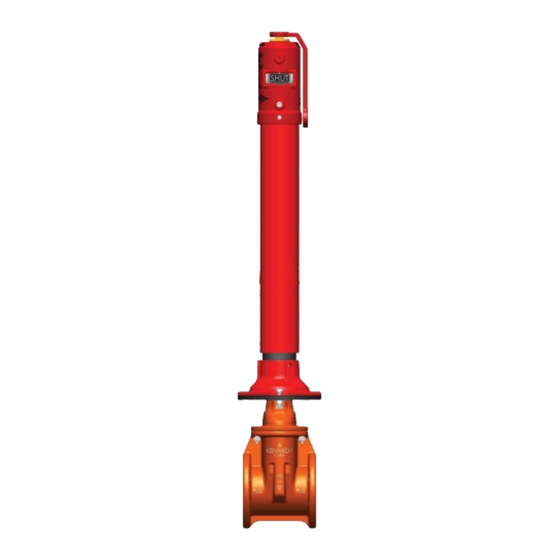
Kennedy 2945 Series Manual

Kennedy 2945 Series Manual

Indicator posts

Advertisement

Quick Links

Section
Style 2945A Adjustable Barrel
Assembly Drawing
Dimensions & Instructions
Style 2945 Fixed Length
Assembly Drawing
Dimensions & Instructions
Style 2945 & 2945A Parts List
Style 2945 & 2945A Trench Depths for Gate Valves
Style 2945 & 2945A Installation & Maintenance
Style 2945 & 2945A Lower Standpipe Change Instructions
Style 2945A Post Extension Instructions
Style 641 Wall Type Indicator Post
Style 641-14 Flanged Base Post Indicator
***Please check our website www.kennedyvalve.com for any product updates and/or changes***
Kennedy Valve
Indicator Posts
2-3
2
3
4-5
4
5
6
7
8-10
11
12
13
14

Advertisement

loading

Summary of Contents for Kennedy 2945 Series

  • Page 1 Kennedy Valve Indicator Posts Section Style 2945A Adjustable Barrel Assembly Drawing Dimensions & Instructions Style 2945 Fixed Length Assembly Drawing Dimensions & Instructions Style 2945 & 2945A Parts List Style 2945 & 2945A Trench Depths for Gate Valves Style 2945 & 2945A Installation & Maintenance 8-10 Style 2945 &...
  • Page 8 Installation – The valve should be opened to the fully open position before proceeding with the Indicator Post installation. Disassembly of the Indicator Post Unit Telescoping Barrel Units • Remove the Top Section from the end of the barrel. • Loosen the two screws on the barrel and slide off the top of the standpipe. Fixed Length Units •...
  • Page 9 Remove the target assembly from inside the body by rotating the operating nut counterclockwise. Loosen the target retainer screws, but do not remove them. Open Left Valves Move the OPEN target to the top of the plate. Note: Position of the SHUT target can be determined by the following chart: Valve Size 4”...
  • Page 10 The target mechanism will travel off the threads of the operating nut in both directions should the targets or target mechanism be positioned incorrectly. Should this happen, readjust targets. If the target mechanism falls from the operating nut, it will be stopped a short distance below the window.
  • Page 11 Place the square socket in the Crane Coupling on the Stem & Coupling sub- assembly over the 2” Square Nut at the top of the stem of the valve. See page F-4 of the Kennedy Valve Product Catalog and follow the directions.
  • Page 12 Instructions for Extending a 2945A Post Loosen the two ¾” screws on top pipe section (near grade line at bottom of pipe) Pull apart the upper section from the lower pipe section. Place new extension coupling with new extension pipe over the existing lower pipe section.

This manual is also suitable for:

2945a series641 series641-14 series