Advertisement
Quick Links
P
r
o
-
B
e
l
L
t
d
P
r
o
-
B
e
l
L
t
d
C
o
n
t
e
n
t
s
C
o
n
t
e
n
t
s
1
1
2
2
2.1
2.2
2.3
2.4
2.5
2.6
3
3
4
4
5
5
6
0
6
3
U
-
0
2
M
A
R
9
9
6
0
6
3
U
-
0
2
M
A
R
9
9
I
n
t
r
o
d
u
c
t
i
o
n
I
n
t
r
o
d
u
c
t
i
o
n
I
n
s
t
a
l
l
a
t
i
o
n
a
n
d
I
n
s
t
a
l
l
a
t
i
o
n
a
n
d
Door removal
Fitting rear connector panels
Setting the mains voltage
Fitting different module types
Connecting the power supply
Monitoring the PSU
T
h
e
o
r
y
o
f
o
p
e
r
a
t
T
h
e
o
r
y
o
f
o
p
e
r
a
t
F
a
u
l
t
f
i
n
d
i
n
g
F
a
u
l
t
f
i
n
d
i
n
g
S
p
e
c
i
f
i
c
a
t
i
o
n
S
p
e
c
i
f
i
c
a
t
i
o
n
c
o
n
f
i
g
u
r
a
t
i
o
n
c
o
n
f
i
g
u
r
a
t
i
o
n
i
o
n
i
o
n
6
0
6
3
R
a
c
k
f
r
a
m
e
6
0
6
3
R
a
c
k
f
r
a
m
e
2
2
4
4
4
4
6
8
13
15
1
7
1
7
1
9
1
9
2
1
2
1
1
1
Advertisement

Subscribe to Our Youtube Channel
Related Manuals for pro bel 6063

Summary of Contents for pro bel 6063
- Page 1 Door removal Fitting rear connector panels Setting the mains voltage Fitting different module types Connecting the power supply Monitoring the PSU...
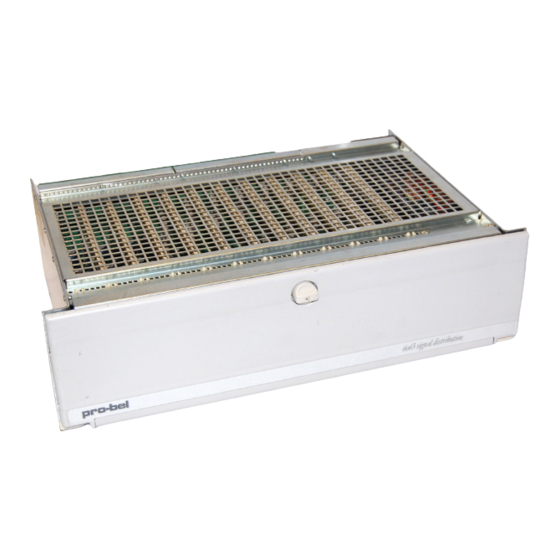
- Page 2 The 6063 rackframe is a 19” wide, 3U high unit offering an extensive mix and match capability for up to 12 modules. Notable characteristics of the rackframe are: • versatility to accommodate different modules • dual mains transformers • robust construction •...
- Page 3 Power supply Mains 1 Optional power supply monitor Power supply Mains 2 12 connector panels...
- Page 4 During the installation process it is important to observe the following points: • do not obstruct the vents on the unit to allow cooling to take place • set the ac supply voltage to the correct local value The door can be removed from the frame by opening it approximately 30° and lifting upwards.
- Page 5 Example connector panels Fixing screw Section of frame Motherboard Socket...
- Page 6 The ac supply voltage is set using voltage selectors fitted to the fuse holders, located in the power supply unit at the rear of the frame, as described opposite. Before commencing, it is essential to disconnect the power from the frame. WARNING: Maintenance of these units should only be carried out by trained service personnel.
- Page 7 Fuse holder and voltage selector Outer catches Fuse holder and voltage selector Voltage selector...
- Page 8 A range of different modules may be accommodated by installing various motherboard sections. The three currently available types are designated ‘type 1’, ‘type 2’ and ‘type 3’. Configuration is usually set at Pro-Bel and does not normally need to be adjusted. However, frames initially supplied with some motherboard sections omitted can be upgraded in the field.
- Page 9 This section is treated as a complete unit comprising a regulator card (1185) and termination assembly. The regulator card provides dc supplies to the converters. It is always used with an ADC and DAC termination assembly (1653) fitted to the rear of the frame.
- Page 10 Socket for rear connection panels Power sockets link to next motherboard section 4 x 6 BNC connectors Fan 1 Fan 2 PSU & Fan monitoring socket System OK Green LED Fan 2 Fail LEDs Fan 1 Fail...
- Page 11 The type 3 motherboard permits five of these cards to be accommodated in the rackframe, alongside other conventional modules. Optical modules are supplied with blanking panels with cut-outs to be fitted to the rear of the frame. The fibre and coaxial connectors protrude through slots in the motherboard and must be secured to the rear panel using a lock washer and retaining nut from the rear of the frame.
- Page 12 Power sockets link to next motherboard section Lock washer Section of motherboard Retaining nut BNC from module Section of card...
- Page 13 The 6063 is fitted with an 1176 dual transformer unit which has an output monitor socket. The unit is electrically connected via flying leads with eyelets that are screwed to the motherboard. Power supplies are fitted from the rear of the frame and are secured by four screws.
- Page 14 Securing screw Retaining clip Monitor socket Fuse holders Retaining clip Securing screw...
- Page 15 There are 4 monitor output connections, two from each transformer. All are ac outputs. Typical output voltage will be 14V to 20Vac depending on loading in the frame. The pins from ac input 1 are labelled +1 and -1 and from ac input 2, +2 and -2. The module has indicator lamps for each ac input to show that an input voltage is present.
- Page 16 Power OK indications ac 1 ac 2 9 way ‘D’ type monitor socket...
- Page 17 The incoming mains is stepped-down via transformers within the power supply unit to 14-0-14 volts. This is connected to the first motherboard section via flying leads from the transformers. It is linked between motherboard sections using power sockets and jumper links. When type 2 modules are used, the regulator card (1185) provides local regulation.
- Page 18 Dual transformer unit Two five slot motherboard sections can be type 1, 2 or 3 Cards inserted from the front Connector panels inserted from the rear REAR OF FRAME Type 2 connector panel is supplied as a single five slot panel...
- Page 19 There is no power from the PSU: • check that the mains is connected • ensure that the correct voltage is selected in the fuseholder • check that the fuse is intact There is no power on the regulator card : •...
- Page 20 Power OK indications Green lamps Mains 1 Mains 2 System OK Green LED Fan 2 Fail LEDs Fan 1 Fail...
- Page 21 Frame size: 3U x 19” x 300mm (depth behind rack) Frame weight: 9kg (typical, fully equipped) Ac input connectors: 2 x chassis mounted IEC plug PSU (1176) fuse type: 1.6A anti-surge 20mm Number and type: 2 x 240/220/120V ac 50/60Hz manually selected (max 253/231/126V ac) Number and type: 2 x green on front of PSU for mains OK...
Need help?
Do you have a question about the 6063 and is the answer not in the manual?
Questions and answers