Table of Contents

Related Manuals for RCF DEC6104

Summary of Contents for RCF DEC6104
- Page 1 FORUM6000 DEC6104 DPS6202 DEC 6104 SCHEDA D’ESPANSIONE DPS 6202 ALIMENTATORE ADDIZIONALE DEC 6104 EXPANDER BOARD DPS 6202 ADDITIONAL POWER SUPPLY UNIT User manual Manuale d’uso the rules of sound...
-
Page 3: Indice - Italiano
INDICE - ITALIANO NOTE SULLA SICUREZZA pag. 4 DESCRIZIONE pag. 6 INSTALLAZIONE DELLA SCHEDA DEC 6104 pag. 6 CONNESSIONI DELLA SCHEDA DEC 6104 pag. 8 PANNELLO FRONTALE DELL’ALIMENTATORE DPS 6202 pag. 9 PANNELLO POSTERIORE DELL’ALIMENTATORE DPS 6202 pag. 10 COLLEGAMENTO TRA LA SCHEDA DEC 6104 E L’ALIMENTATORE DPS 6202 pag. - Page 4 L’installazione e l’utilizzo errati dei prodotti esimono la RCF S.p.A. da ogni responsabilità.. ATTENZIONE: Per prevenire i rischi di fiamme o scosse elettriche, non esporre mai questi prodotti alla pioggia o all’umidità.
-
Page 5: Note Importanti
Verificare inoltre l’idoneità del supporto (parete, soffitto, struttura ecc.) e dei componenti utilizzati per il fissaggio (tasselli, viti, staffe non fornite da RCF ecc.) che devono garantire la sicurezza dell’impianto / installazione nel tempo, anche considerando, ad esempio, vibrazioni meccaniche normalmente generate da un trasduttore. - Page 6 RCF S.p.A. Vi ringrazia per l’acquisto di questi prodotti, realizzati in modo da garantirne l’affidabilità e prestazioni elevate. DESCRIZIONE La scheda DEC 6104 si installa nell’unità centrale DMU 6100 del sistema per conferenze RCF FORUM 6000, implementandone ed espandendone le caratteristiche: •...
- Page 7 DMU 6100 sia “330.32.388-REV.A”; in caso contrario, contattare la sede principale di RCF S.p.A. L’indicazione è posta sulla stessa scheda madre vicino al logo RCF: Individuare il processore, i connettori per i cavi “flat cable”, il connettore TP1 ed il jumper JP9 sulla scheda madre dell’unità...
- Page 8 Collegare la coppia di conduttori rosso e nero della scheda d’espansione DEC 6104 al connettore TP1 della scheda madre dell’unità centrale DMU 6100. Nota: il filo rosso è collegato al contatto “+VS”; il filo nero a “A-GND”. Posizionare la scheda d’espansione DEC 6104 (in modo che i suoi connettori siano nello spazio prima occupato dalla pannello cieco posteriore dell’unità...
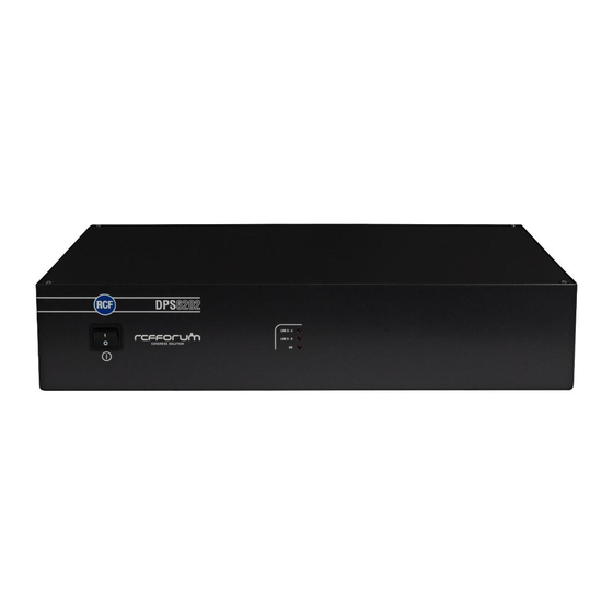
- Page 9 LINE 6 Porta per il collegamento della sesta linea composta da max. 30 console microfoniche DMS 6410. Porta USB (2.0) per il collegamento con un PC. 6 LED di segnalazione: (quando acceso) porta USB attiva (lampeggiante) dati in ricezione (lampeggiante) dati in trasmissione (quando acceso) alimentazione delle linee 3 –...
- Page 10 PANNELLO POSTERIORE DELL’ALIMENTATORE DPS 6202 Uscita con connettore XLR a 7 poli per l’alimentazione della scheda DEC 6104. – POWER ON, comando di attivazione dell’alimentatore DPS 6202 – GROUND, massa – 24 V, alimentazione addizionale per la gestione del segnale delle console mic. DMS 6410 –...
- Page 11 INSERIMENTO DEL PROCESSORE “ANTI-FEEDBACK” La scheda DEC 6104 incorpora un processore “anti-feedback”, utile per ridurre le eventuali ret- roazioni incontrollate del segnale audio (che causano fischi fastidiosi) dovute alla vicinanza tra diffusori e microfoni, al volume alto dei diffusori acustici ed all’apertura di molti microfoni contem- poraneamente.
-
Page 12: Dati Tecnici
IMPOSTAZIONE DEL PROCESSORE ANTI-FEEDBACK Nel menù di configurazione dell’unità centrale DMU 6100, è ora presente un nuovo parametro di configurazione inerente all’impostazione del processore “anti-feedback”. Tener premuto per almeno 3 secondi il tasto SET dell’unità centrale DMU 6100 per accedere al menù... -
Page 13: Esempio Di Collegamento
ESEMPIO DI COLLEGAMENTO » » » » » IN A IN B L1/L2 PLAY TELECONF... -
Page 14: Important Notes
RCF dealer. The metallic parts of the DPS 6202 power supply unit are earthed by means of the power cable. -
Page 15: Operating Precautions
(screw anchors, screws, brackets not supplied by RCF etc.), which must guarantee the security of the system / installation over time, also considering, for example, the mechanical vibrations normally generated by transducers. - Page 16 RCF S.p.A. thanks you for purchasing these products, which have been designed to guarantee reliability and high performances. DESCRIPTION The DEC 6104 board is to be installed into the DMU 6100 main unit of the RCF FORUM 6000 conference system. This board adds features: •...
- Page 17 Before proceeding, verify that the DMU 6100 motherboard part number is ‘330.32.388-REV.A’; if not, contact your RCF dealer. The part number is indicated on the motherboard, close to the RCF logo: Look at the DMU 6100 motherboard to realise where the CPU, the flat cable...
- Page 18 Connect the red / black wire pair of the DEC 6104 board to the DMU 6100 motherboard TP1 socket. Note: the red wire is to be connected to the ‘+VS’ terminal; the black wire to ‘A-GND’. Place the DEC 6104 board (its ports shall occupy the DMU 6100 rear panel part where the blank panel was) and firmly fix it through the 2 screws.
- Page 19 port (2.0) for PC connection. 6 LEDs: (when lit) USB port operating (when flashing) data receiving (when flashing) data transmitting (when lit) line 3 – 4 power on (from DPS 6202) (when lit) line 5 – 6 power on (from DPS 6202) (when lit) DEC 6104 internal CPU operating properly RS 485 serial port for a long distance connection to a PC.
- Page 20 DPS 6202 POWER SUPPLY UNIT REAR PANEL Power output (7-pin XLR connector) to the DEC 6104 board. – POWER ON (DPS 6202 power on command) – GROUND – 24 V (additional power to manage DMS 6410 mic. console audio signals) –...
- Page 21 ANTI-FEEDBACK PROCESSOR INSERTION The DEC 6104 board has an anti-feedback processor useful to reduce possible uncontrolled feedbacks of the audio signal (sound loops that cause annoying whistles) due to loudspeakers too close to microphones, loudspeaker high volume and many open microphones at the same time. After installing the DEC 6104 board, the anti-feedback processor is already inserted in the audio path of the DMU 6100 central unit ‘MAIN OUT’.
-
Page 22: Specifications
ANTI-FEEDBACK PROCESSOR SETTING The DMU 6100 software now includes a new parameter concerning the anti-feedback processor setting. Press and hold (for at least 3 seconds) the SET button of the DMU 6100 main unit to enter the config- uration menu, then press it again repeatedly to scroll all parameters until ‘AFP SETUP’ is displayed. Use the buttons to change the setting (if necessary only), then press ENTER to confirm (the system is rebooted). -
Page 23: Example Of Connections
EXAMPLE OF CONNECTIONS » » » » » IN A IN B L1/L2 PLAY TELECONF... - Page 24 Except possible errors and omissions. RCF S.p.A. reserves the right to make modifications without prior notice. the rules of sound RCF SpA: Via Raffaello, 13 - 42010 Reggio Emilia Italy > tel. +39 0522 274411 - fax +39 0522 274484 - e-mail: rcfservice@rcf.it...
Need help?
Do you have a question about the DEC6104 and is the answer not in the manual?
Questions and answers