Table of Contents
Advertisement
Quick Links
IMPORTANT NOTES
This V2.00 Quick Start Guide is for AIT5000 units manufactured after March 2020, that feature a new wireless
Web Interface and which are identified by a wireless network name (SSID) of "DY-AIS-xxxx". If your AIT5000
transmits a wireless network name of "DY-AIT5000-xxxx" please refer to V1.00 Quick Start Guide.
If you intend to permanently connect the AIT5000 to an onboard computer via USB, we recommend using our
NMEA to USB Adaptor cable for extra protection against static discharges and supply voltage spikes.
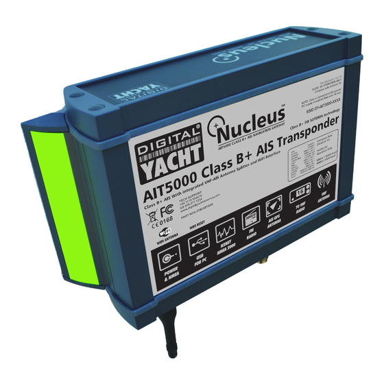
AIT5000
CLASS B+ AIS
TRANSPONDER
Advertisement
Table of Contents

Subscribe to Our Youtube Channel
Related Manuals for DIGITAL YACHT AIT5000


Summary of Contents for DIGITAL YACHT AIT5000
- Page 1 IMPORTANT NOTES This V2.00 Quick Start Guide is for AIT5000 units manufactured after March 2020, that feature a new wireless Web Interface and which are identified by a wireless network name (SSID) of “DY-AIS-xxxx”. If your AIT5000 transmits a wireless network name of “DY-AIT5000-xxxx” please refer to V1.00 Quick Start Guide.
-
Page 2: Before You Start
This Quick Start Guide will provide basic information on the AIT5000 to allow you to install and get the AIT5000 working, we suggest that you consult the manufacturer’s user manuals for any other equipment that you will be connecting the AIT5000 to. - Page 3 Installation Step 2 – Mechanical Fixings • Access to the fixing holes is achieved by removal of the two green decal strips down each side of the AIT5000. Once fixed in place, the green decal strips can be clicked back in place.
- Page 4 The most common connection to a dedicated chart plotter is to take the NMEA Output 1 (Orange+ and Brown –) from the AIT5000 Transponder and to connect it to a free NMEA Input on the plotter. You must then tell the chart plotter that AIS data is connected to this port and set the baud rate to 38,400 Baud –...
- Page 5 USB cable without the use of a powered extender cable or Hub is 5m. • Please do not plug in the USB cable of the AIT5000 to your PC. We will cover this in section 4 - Configuration. Installation Step 7 – Remote Switch •...
-
Page 6: Network Settings
AIT5000 uses (Channel 1 by default). If you already have a wireless network on the boat and you would prefer the AIT5000 to be part of this network, rather than create another wireless network of its own, you can make it operate in “Station”... - Page 7 AIT5000 Web Interface Quick Start Guide for AIT5000 V2.00 TEL + 44 1179 554474 www.digitalyacht.co.uk sales@digitalyacht.co.uk...
- Page 8 20 seconds. By default, the AIT5000 transmits wireless NMEA data in UDP mode which is the easiest mode to setup in most apps – just tell the app that the UDP data is on port 2000 and it should start receiving data. In some apps, such as the popular Navionics Boating app, the AIT5000 will even be detected automatically and no app setup is required.
-
Page 9: Ais Status
TX count to show how many targets have been received and how many successful transmissions the AIT5000 has made. Please note that when you first display this web page, you will need to wait until the AIT5000 makes a transmission before it can check/tick the “AIS Antenna”... -
Page 10: Vessel Details
If you leave the AIT5000 in “Silent Mode” for more than a few minutes, the green “Power” LED will go off and the yellow “Timeout” LED will illuminate. To start transmitting again, simply click the “Silent” button again and the blue “Silent” LED will go off and as soon as the AIT5000 makes its next transmission the green “Power”... -
Page 11: Firmware Update
Correct operation should be verified as follows: 1. Check that the green “Wi-Fi” LED flashes when you first turn the AIT5000 on and goes to a solid ON, as soon as you have connected wirelessly to the AIT5000 (Access Point Mode) or it has successfully joined another wireless network (Station Mode). -
Page 12: Troubleshooting
4. Is there a good supply voltage? Check in the web interface if the DC supply is higher than 9.8v which is the level at which the AIT5000 will stop transmitting. It needs a good 12v or 24v supply for correct operation and you will need to check the power connections for excessive voltage drop.
Need help?
Do you have a question about the AIT5000 and is the answer not in the manual?
Questions and answers