Table of Contents
Advertisement
Quick Links
System Board 6331
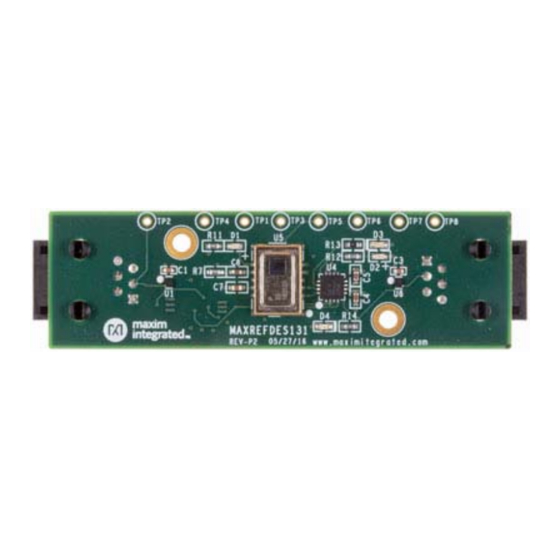
MAXREFDES131#: 1-WIRE GRID-EYE SENSOR
MAXREFDES131# is a sensing solution featuring the Panasonic AMG8833 Grid-EYE®
and the Maxim 1-Wire
sensing, people counting, and gestures while tethered up to 100m along the 1-Wire bus.
The board features RJ-11 connectors and convenient mounting holes for quick
evaluation and implementation.
Example source code for interfacing with MAXREFDES131# is available for both Arm
mbed
and Arduino
™
a hardware 1-Wire shield. A demonstration GUI allows for visual feedback of up to 10
daisy-chained MAXREFDES131# 1-Wire Grid-EYE sensors.
As with all Maxim reference designs, the BOM, schematics, layout files, and fab files are
all available from the Design Resources tab. In addition, boards are available for
purchase.
Features
1-Wire network
Flexible location
Sleep mode
Example source code
Demonstration GUI
Competitive Advantages
Extended range
Compact
Power-conserving sleep mode
Cost effective
bus, enabled by the DS28E17. The system enables presence
®
platforms. This design conveniently works with MAXREFDES132#,
®
®
Advertisement
Table of Contents

Subscribe to Our Youtube Channel
Related Manuals for Maxim Integrated MAXREFDES131


Summary of Contents for Maxim Integrated MAXREFDES131
- Page 1 100m along the 1-Wire bus. The board features RJ-11 connectors and convenient mounting holes for quick evaluation and implementation. Example source code for interfacing with MAXREFDES131# is available for both Arm ® mbed and Arduino platforms.
- Page 2 Clearly, critical components of IoT applications will ensure the safety of people and buildings, movement of commerce, and activation of features. For these reason, MAXREFDES131# is the future of IoT. This unique system marries a high-performance passive IR-sensing array, Panasonic’s Grid- EYE, with Maxim’s 1-Wire bus, for enhanced range and simple interface.
- Page 3 After the user presses the “Enumerate Sensors” button, the firmware responds with a message containing the number of MAXREFDES131# units attached to the 1-Wire bus. In addition, the “Select Sensor” dropdown will be enabled. After the user selects a sensor from the dropdown list, the “Receive Data” push button will be enabled.
- Page 4 The firmware consists of an interrupt service routine (ISR) that receives commands from the demonstration GUI and sets the demo state based on those commands. A switch statement in the main loop evaluates the state. Figure 2. MAXREFDES131 GUI flowchart. Figure 3. MAXREFDES131 Firmware flowchart.
- Page 5 Figure 4. Master selection for mbed demo program. 1. Compile and download the resulting binary to your platform. 2. Connect MAXREFDES131# to the 1-Wire bus with the provided cable. 3. Reset the mbed platform. 4. Navigate to where you installed the MAXREFDES131DemoV1.00 folder.
- Page 6 1-Wire is a registered trademark of Maxim Integrated Products, Inc. Arduino is a registered trademark of Arduino LLC. ARM and mbed are registered trademarks of ARM Holdings. Grid-EYE is a registered trademark of Panasonic Corporation. Windows is a registered trademark and registered service mark of Microsoft Corporation.
Need help?
Do you have a question about the MAXREFDES131 and is the answer not in the manual?
Questions and answers