
Related Manuals for DeZurik PPE Series


Summary of Contents for DeZurik PPE Series
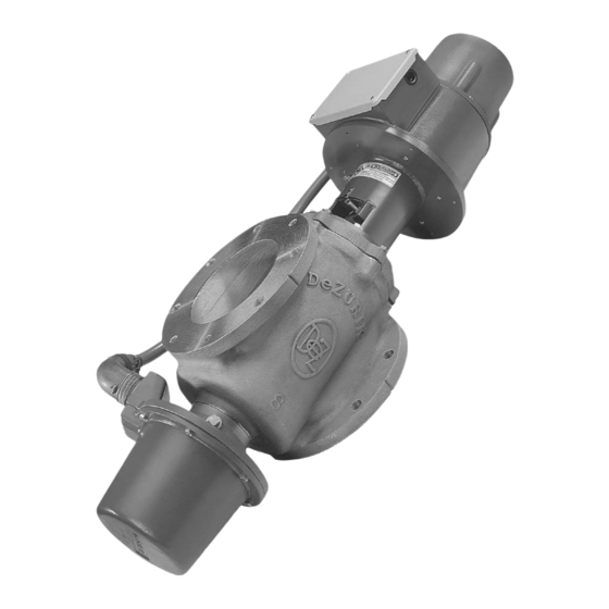
- Page 1 PPE, 4 – 20 inch Precision Electric Control Valves and Control Stations D11014 Instruction August 2018...
- Page 2 Recommended spare parts are listed on the assembly drawing. These parts should be stocked to minimize downtime. Order parts from your DeZURIK sales representative, or directly from DeZURIK. When ordering parts, please include the 7-digit part number and 4-digit revision number (example: 9999999R000) located on the data plate attached to the valve assembly.
-
Page 3: Table Of Contents
PPE, 4 – 20 inch Precision Electric Control Valves and Control Stations __________________________________________________________________________ TABLE OF CONTENTS SECTION PAGE Description - - - - - - - - - - - - - - - - - - - - - - - - - - - - - - - - - - - - - - - - - - - - - - - - - - - - - - - - - - - - - - - - - Lubrication - - - - - - - - - - - - - - - - - - - - - - - - - - - - - - - - - - - - - - - - - - - - - - - - - - - - - - - - - - - - - - - - - AC Power Requirements - - - - - - - - - - - - - - - - - - - - - - - - - - - - - - - - - - - - - - - - - - - - - - - - - - - - - - - Alignment Tool Set- - - - - - - - - - - - - - - - - - - - - - - - - - - - - - - - - - - - - - - - - - - - - - - - - - - - - - - - - - - -... -
Page 4: Description
Valve speed of operation is 20% longer when using 50 Hertz power. Alignment Tool Set DeZURIK offers an alignment tool set that is used to adjust limit switches and potentiometers, and is also needed whenever the Control Module of the valve is serviced. This tool set contains DeZURIK tool numbers G-2125 and G-2139, and can be ordered through your local DeZURIK representative using Part Number 1202324. -
Page 5: Valve Disassembly
PPE, 4 – 20 inch Precision Electric Control Valves and Control Stations __________________________________________________________________________ Valve Disassembly To safely remove the valve from the pipeline, carefully follow these steps. Relieve pipeline pressure. Turn off all electrical power to the valve. This valve operates with a powered actuator. Disconnect and lock out the electrical power to prevent accidental operation of the actuator. - Page 6 PPE, 4-20 inch Precision Electric Control Valves and Control Stations __________________________________________________________________________ Valve Disassembly (continued) Remove the Control Module, being careful not to rotate the lever on the Control Module shaft. Remove the screw which fastens the stem extension shaft to the bottom of the plug journal. Remove the four screws which fasten the adaptor to the bottom of the valve.
-
Page 7: Valve Reassembly
PPE, 4 – 20 inch Precision Electric Control Valves and Control Stations __________________________________________________________________________ Valve Reassembly Be sure the plug journal, body and bonnet bearings are clean and dry, and that any spacers removed during disassembly are placed in the proper location on the plug journals. Slide the plug into the valve body. -
Page 8: Table B - Fastening Torque For Harmonic Drive Components
PPE, 4-20 inch Precision Electric Control Valves and Control Stations __________________________________________________________________________ Valve Reassembly (continued) Fasten the flexspline to the plug stem; if the circular spline has been removed, fasten it to the motor plate or adaptor, depending on your type or size of valve. Install the screws dry, and tighten them to the torque shown in Table B. -
Page 9: Motor Replacement
Control Module adaptor. Use DeZURIK alignment tool G-2125 for true alignment. When this alignment is correct, tighten the clamping screw in the lever. - Page 10 PPE, 4-20 inch Precision Electric Control Valves and Control Stations __________________________________________________________________________ Motor Replacement (disassembly, continued) This valve operates with a powered actuator. Disconnect and lock out the electrical power to prevent accidental operation of the actuator. Disconnect the Amphenol connector from the Control Module. Remove the six screws which fasten the motor cover to the motor housing, and remove the cover.
-
Page 11: Figure 3 - Exploded View For New Style Harmonic Drive
PPE, 4 – 20 inch Precision Electric Control Valves and Control Stations __________________________________________________________________________ Figure 3 - Exploded View for New Style Harmonic Drive _________________________________________________________________________________ August 2018 Page D11014... -
Page 12: Figure 4 - Hub And Pin Dimensions
PPE, 4-20 inch Precision Electric Control Valves and Control Stations __________________________________________________________________________ Motor Replacement (reassembly) Attach the slip clutch to the top motor shaft of the new motor. The new motor may have a hole drilled in place for the wave generator hub. If this pin hole is in place go to step 6 to continue with the next steps of assembly. -
Page 13: Figure 5 - Wave Generator Components, In Sequence Of Installation
PPE, 4 – 20 inch Precision Electric Control Valves and Control Stations __________________________________________________________________________ Motor Replacement (reassembly, continued) Slide the hub onto the motor shaft until the pinning holes line up. Drive a 0.125 diameter pin into the holes. Be sure the connection is tight and that the pin is engaged to a point flush or slightly below the surface of the hub. -
Page 14: Limit Switch Replacement
PPE, 4-20 inch Precision Electric Control Valves and Control Stations __________________________________________________________________________ Motor Replacement (reassembly, continued) When the correct alignment has been obtained, remove the inspection tools and screw the pipe plug back into the side of the adaptor. 12 Fasten the motor housing to the adaptor and attach the safety interlock switch to the motor housing. -
Page 15: Control Module Replacement
PPE, 4 – 20 inch Precision Electric Control Valves and Control Stations __________________________________________________________________________ Limit Switch, Potentiometer or Resolver Replacement (installation) Mount the new device into its receptacle in the Control Module mounting plate with the cleat clamps. Slide the gear and clamp onto the device shaft, making sure that the gear meshes correctly with the mating gear. -
Page 16: Adjustments
PPE, 4-20 inch Precision Electric Control Valves and Control Stations __________________________________________________________________________ Adjustments, Packing If the packing leaks, tighten the gland nuts in equal ¼-turn increments, however only enough to stop the leak. Do not continue tightening after the leakage stops. If the packing leakage cannot be stopped by tightening the gland nuts, the packing rings must be replaced. -
Page 17: Figure 6 - Top View Of Limit Switch
PPE, 4 – 20 inch Precision Electric Control Valves and Control Stations __________________________________________________________________________ Adjustments, Closed Position Switch, (No.1 Closed Limit & No.3 Auxiliary, Continued) 11 Manually rotate the switch shaft until the red line is positioned as shown in Figure 6. 12 Tighten the screw in the clamp that holds the gear to the switch shaft. -
Page 18: Open Position Switches
PPE, 4-20 inch Precision Electric Control Valves and Control Stations __________________________________________________________________________ Adjustments, Closed Position Switch, (No.1 Closed Limit & No.3 Auxiliary, Continued) 15 Turn Adjust Screw “B” of switch No.1 (No.3 if auxiliary) counterclockwise until the switch opens or a stop is reached. a. -
Page 19: Potentiometer Adjustment - Using 5 Volt Dc Power Supply
PPE, 4 – 20 inch Precision Electric Control Valves and Control Stations __________________________________________________________________________ Adjustments, Open Position Switch, (No.2 Closed Limit & No.4 Auxiliary, continued) Loosen Lock Screw “A” of switch No.2 (No.4 if auxiliary). Turn Adjust Screw “A” of switch No.2 (No.4 if auxiliary) clockwise until the switch opens or a stop is reached. - Page 20 PPE, 4-20 inch Precision Electric Control Valves and Control Stations __________________________________________________________________________ Potentiometer Adjustment; Using a 5 Volt DC Power Supply (continued) Remove the six screws which fasten the Control Module cover to the control module, and remove the cover. Remove the four screws which fasten the Control Module to the adaptor at the bottom of the valve.
-
Page 21: Potentiometer Adjustment - Using An Ohmmeter
PPE, 4 – 20 inch Precision Electric Control Valves and Control Stations __________________________________________________________________________ Potentiometer Adjustment; Using an Ohmmeter NOTE: The potentiometer can be adjusted on the valve or by using the Alignment Tool G-2139. Move the valve to the closed position. This valve operates with a powered actuator. -
Page 22: Resolver Adjustment - Using 24 Volt Dc Power Supply
PPE, 4-20 inch Precision Electric Control Valves and Control Stations __________________________________________________________________________ Potentiometer Adjustment; Using an Ohmmeter (continued) 16 Check the resistance value between terminals “CCW” & “S”. To make a final, fine adjustment of this value loosen the servo mount clamp screws, and rotate the potentiometer body slightly until the resistance is 4 percent of the value recorded in step 11. - Page 23 PPE, 4 – 20 inch Precision Electric Control Valves and Control Stations __________________________________________________________________________ Resolver Adjustment; Using a 24VDC Power and Ammeter (continued) Attach the alignment tool and rotate the Control Module lever so the removable pin in the alignment tool fits into the hole in the longer arm of the tool and into the slot of the Control Module lever.
-
Page 24: Open Position Switches, When Using A Resolver
PPE, 4-20 inch Precision Electric Control Valves and Control Stations __________________________________________________________________________ Resolver Adjustment; Using a 24VDC Power and Ammeter (continued) 25 Locate terminal screws “29”, “30” & “31” in the junction box. 26 Connect the positive “+” wire of the 24 VDC power supply to terminal 29 in the junction box. 27 Connect the negative “-“... - Page 25 PPE, 4 – 20 inch Precision Electric Control Valves and Control Stations __________________________________________________________________________ Adjustment, Resolver, Open Position Switch (continued) Connect and ohmmeter to terminals “C” and “NO” of switch No.2 (switch no.4 when setting the auxiliary). NOTE: When adjusting the Adjust Screws, always loosen the Lockscrew first, and retighten this Lockscrew before proceeding with the next step.
-
Page 26: Wiring
PPE, 4-20 inch Precision Electric Control Valves and Control Stations __________________________________________________________________________ Control Station Wiring Before connecting a Control Station to the valve it is necessary to identify your control station (Analog or Time Duration, with or without a Part Number stamped on the front cover). Older Control Stations will not have the Part Number stamped on the front. - Page 27 PPE, 4 – 20 inch Precision Electric Control Valves and Control Stations __________________________________________________________________________ Connecting a Time Duration Station (Part number stamped on case, continued) • If the valve wiring has jumpers between terminals 3 and 10, and 2 and 7, they must be changed so they are as described in the paragraph immediately above.
- Page 28 PPE, 4-20 inch Precision Electric Control Valves and Control Stations __________________________________________________________________________ Connecting an Analog Control Station (Part number stamped on front of case, continued) o Change the OPEN wire (No.7) coming from the control station, from the valve terminal 9 to valve terminal 7. o Change the CLOSE wire (No.6) coming from the control station, from valve terminal 12 to valve terminal 10.
- Page 29 PPE, 4 – 20 inch Precision Electric Control Valves and Control Stations __________________________________________________________________________ Connecting an Analog Control Station (Without part number stamped on station case) See Schematic No.4 for reference. This valve operates with a powered actuator, Disconnect and lock out the electrical power to prevent accidental operation of the actuator.
- Page 30 PPE, 4-20 inch Precision Electric Control Valves and Control Stations __________________________________________________________________________ Connecting a Time Duration Control Station and Resolver (Part number stamped on control station case) Remove the junction box cover from the valve, and check the location of the jumper wires on the valve’...
-
Page 31: Description Of Features
PPE, 4 – 20 inch Precision Electric Control Valves and Control Stations __________________________________________________________________________ Control Stations, Descriptions of Features Both types of control station (Analog and Time Duration) have push-button switches to operate the valve manually. Both types also have a digital display that shows valve position, and indicating lights that show when the valve is fully closed, fully open or moving. -
Page 32: Control Stations
PPE, 4-20 inch Precision Electric Control Valves and Control Stations __________________________________________________________________________ Control Stations Figure 7 Control Stations, Indicator Lights Lights while valve is being driven in either direction under manual or automatic control. OPEN LIMIT Lights when valve has reached fully open position, indicating that power has been disconnected from motor by the limit switch. -
Page 33: Display Adjustment
With an Analog Control Station, the valve is fully closed at a minimum signal, and is fully open at the maximum signal. Valve position is directly proportional to the input signal for intermediate positions. DeZURIK Analog Control Stations are available with 1-5 mA, 4-20 mA, 10-50 mA, or 1-5 volt signal ranges. -
Page 34: Time Durations Station (Cpe101, Cpe102)
PPE, 4-20 inch Precision Electric Control Valves and Control Stations __________________________________________________________________________ Analog Control Station (Control Station Adjustment, continued) Figure 8 With the control station in AUTO mode, connect a signal source to the analog input terminals and adjust it to the minimum signal level. With the signal at its minimum level, set the “OFFSET potentiometer so that the valve reaches its fully closed position, but is not overdriven. -
Page 35: Schematic No 1 - Time Duration Control (Current Models)
PPE, 4 – 20 inch Precision Electric Control Valves and Control Stations __________________________________________________________________________ Time Duration Control Station (Schematic No.1) Control Station with Part Number stamped on Front. Supply Power: 120 Volts AC (Control Station fused at 2 Amps.) Control Station Terminal No.1 = L1 Control Station Terminal No.2 = L2 Control Station Terminal No.3 = Ground Signal Connection:... -
Page 36: Schematic No 2 - Analog Control (Current Models)
PPE, 4-20 inch Precision Electric Control Valves and Control Stations __________________________________________________________________________ Analog Control Station (Schematic No. 2) Control Station with Part Number stamped on Front Supply Power: 120 Volts AC (Control Station fused at 2 Amps.) Control Station Terminal No.1 = L1 Control Station Terminal No.2 = L2 Control Station Terminal No.3 = Ground Valve Signal Connection:... -
Page 37: Schematic No 3 - Time Duration Control (Earlier Models)
PPE, 4 – 20 inch Precision Electric Control Valves and Control Stations __________________________________________________________________________ Time Duration Control Station (Schematic No. 3) Control Station without Part Number stamped on Front. Supply Power: 120 Volts AC (Control Station fused at 2 Amps.) Control Station Terminal No.1 = L1 Control Station Terminal No.2 = L2 Control Station Terminal No.3 = Ground Valve Signal Connection:... -
Page 38: Schematic No 4 - Analog Control (Earlier Models)
PPE, 4-20 inch Precision Electric Control Valves and Control Stations __________________________________________________________________________ Analog Control Station (Schematic No. 4) Control Station without Part Number stamped on Front Supply Power: 120 Volts AC (Control Station fused at 2 Amps.) Control Station Terminal No.1 = L1 Control Station Terminal No.2 = L2 Control Station Terminal No.3 = Ground Valve Signal Connection:... - Page 39 PPE, 4 – 20 inch Precision Electric Control Valves and Control Stations __________________________________________________________________________ Time Duration Control Station and Resolver (Schematic No.5) Control Station with Part Number stamped on Front. Supply Power: 120 Volts AC (Control Station fused at 2 Amps.) Control Station Terminal No.1 = L1 Control Station Terminal No.2 = L2 Control Station Terminal No.3 = Ground...
-
Page 40: Schematic No 5 - Time Duration Control Plus Resolver
PPE, 4-20 inch Precision Electric Control Valves and Control Stations __________________________________________________________________________ Connecting a Time Duration Control Station and Resolver (Schematic No. 5) ──────┤ ├────── Valve Control Station _________________________________________________________________________________ D11014 Page August 2018... - Page 41 If you use metric fasteners with ASME Class 150/300 bolt holes and flange bolt patterns, you do so at your sole risk and any liability associated with such use shall not be the responsibility of DeZURIK, Inc. In addition to the foregoing, DeZURIK’s Manufacturer’s Conditions apply.
Need help?
Do you have a question about the PPE Series and is the answer not in the manual?
Questions and answers