
Subscribe to Our Youtube Channel
Related Manuals for DeZurik BAW AWWA


Summary of Contents for DeZurik BAW AWWA
- Page 1 DeZURIK 20–144" BAW AWWA BUTTERFLY VALVES WITH EPOXY-RETAINED SEAT D10373 Instruction April 2017...
- Page 2 Inspection Your BAW AWWA Butterfly Valve has been packaged to provide protection during shipment; however, it can be damaged in transport. Carefully inspect the unit for damage upon arrival and file a claim with the carrier if damage is apparent.
-
Page 3: Table Of Contents
DeZURIK 20-144” BAW AWWA Butterfly Valves with Epoxy-Retained Seat Table of Contents Description - - - - - - - - - - - - - - - - - - - - - - - - - - - - - - - - - - - - - - - - - - - - - - - - - - - - -... -
Page 4: Description
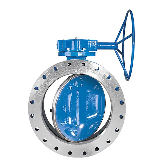
Butterfly Valves with Epoxy-Retained Seat Description The 20-120” BAW AWWA Butterfly Valve is a resilient seated valve, which conforms to all of the AWWA C504 requirements. DeZURIK offers the BAW AWWA Butterfly Valve in a mechanical joint end style per ANSI/AWWA C111/A 21.11-85 in the 20–48" size range. The flanged end style is available in all sizes. -
Page 5: Drawings
DeZURIK 20-144” BAW AWWA Butterfly Valves with Epoxy-Retained Seat Drawings Figure 1 - 20–48" BAW AWWA Butterfly Valves April 2017 Page 5 D10373... - Page 6 DeZURIK 20-144” BAW AWWA Butterfly Valves with Epoxy-Retained Seat Drawings (Continued) Figure 2 - 54–144" BAW AWWA Butterfly Valves April 2017 Page 6 D10373...
-
Page 7: Installation
Butterfly Valves with Epoxy-Retained Seat Installation Requirements DeZURIK recommends installing BAW AWWA Butterfly Valves with seat side upstream. Whenever possible, install the valve with the shaft horizontal to provide a self-cleaning action on the seat and disc. Refer to the installation drawing. -
Page 8: All Valves
On valves with adjustable packing, the actuator or mounting bracket must be designed so it does not interfere with the packing gland or hinder packing gland adjustment. For information regarding installation of a DeZURIK actuator, see the instruction for that actuator. Packing Adjustment If the packing leaks on valves without packing gland the packing can be adjusted by removing the actuator, sliding a .03"... -
Page 9: Packing Replacement
DeZURIK 20-144” BAW AWWA Butterfly Valves with Epoxy-Retained Seat wear. If packing leakage cannot be stopped by tightening the packing gland nuts, the packing must be replaced. Packing Replacement To replace the packing, you will need the following: A set of new packing ... -
Page 10: Valves With Packing Gland
DeZURIK 20-144” BAW AWWA Butterfly Valves with Epoxy-Retained Seat Packing Replacement (Continued) Valves with Packing Gland 1. Close the valve and relieve pipeline pressure. Moving parts from accidental operation of power actuator can cause personal injury or equipment damage. Disconnect and lock out power to actuator before servicing. -
Page 11: Disassembling Valve
DeZURIK 20-144” BAW AWWA Butterfly Valves with Epoxy-Retained Seat Disassembling Valve Before disassembly, remove the valve from the pipe line, open the valve and remove actuator (and adapter, if included) from the valve. Moving parts from accidental operation of power actuator can cause personal injury or equipment damage. -
Page 12: Reassembling Valve
DeZURIK 20-144” BAW AWWA Butterfly Valves with Epoxy-Retained Seat Reassembling Valve (Continued) Reassembling Valve 1. Block the body (A1) in a horizontal position with the seat facing down. 2. Holding the disc (A11) in a horizontal position with the shaft connection toward the top of body (A1). -
Page 13: Final Assembly
DeZURIK 20-144” BAW AWWA Butterfly Valves with Epoxy-Retained Seat Reassembling Valve (Continued) Final Assembly 1. Secure the adjusting screw and jam nut in the bottom of lower shaft with Primer and Loctite. 2. Make sure that the bearing is within 1/8" of the valve port when seated in the shaft bore. -
Page 14: Seat Adjustment
To adjust the seat, order the seat adjustment kit from your DeZURIK service center listed on the back cover. Seat Replacement To replace the seat, order the seat replacement kit from your DeZURIK service center listed on the back cover. Troubleshooting...
Need help?
Do you have a question about the BAW AWWA and is the answer not in the manual?
Questions and answers