Accudyne Industries Milton Roy MILROYAL C Installation, Operation & Maintenance Manual
Hide thumbs
Also See for Milton Roy MILROYAL C:
Table of Contents
Advertisement
Quick Links
Advertisement
Table of Contents

Related Manuals for Accudyne Industries Milton Roy MILROYAL C


Summary of Contents for Accudyne Industries Milton Roy MILROYAL C
- Page 1 MILROYAL C DRIVE ® IOM Manual Manual No : 53939 Rev. : 00 Rev. Date : 11/2015...
- Page 3 PRECAUTIONS The following precautions should be taken when working with metering pumps. Please read this section carefully prior to installation. Protective Clothing ALWAYS wear protective clothing, face shield, safety glasses and gloves when working on or near your metering pump. Additional precautions should be taken depending on the solution being pumped.
- Page 4 Lifting This manual should be used as a guide only - Follow your company’s recommended lifting procedures. It is not intended to replace or take precedence over recommendations, policies and procedures judged as safe due to the local environment than what is contained herein. Use lifting equipment that is rated for the weight of the equipment to be lifted.
-
Page 5: Table Of Contents
TABLE OF CONTENTS SECTION 1 - GENERAL DESCRIPTION . . . . . . . . . . . . . . . . . . . . . . . . . . . . . . . . . . . . . . . . . . . . . . . . . . . . . . . 2 1.1 INTRODUCTION . - Page 6 3.4 FILLING PUMP SYSTEM ............14 3.5 PREVENTATIVE MAINTENANCE.
-
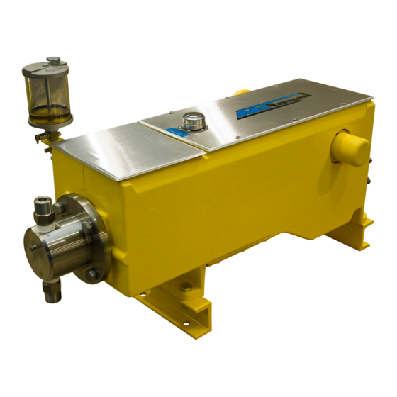
Page 7: List Of Illustrations Figure 1. Milroyal ® C Metering Pump
Figure 1. Milroyal C Metering Pump. ® Installation, Operations & Maintenance Manual... -
Page 8: Section 1 - General Description
SECTION 1 - GENERAL DESCRIPTION 1.1 INTRODUCTION 1.3 PRINCIPLE OF OPERATION The Milroyal C is a reciprocating positive- The drive unit moves the pump plunger to draw ® displacement controlled-volume pump designed to liquid into the liquid end on the suction stroke move specific volumes of liquid against a positive and to expel the liquid on the subsequent pressure differential between the pump suction... -
Page 9: Figure 3. Packed Plunger Liquid End (Shown With Optional Oiler) (See Manual 54270)
SECTION 1 - GENERAL DESCRIPTION As the plunger reciprocates in the liquid end, In packed plunger liquid ends, the plunger contacts the pumped liquid is alternately drawn into and the process liquid, while diaphragm liquid ends discharged from the liquid end. Each suction isolate the process liquid from the pump plunger. -
Page 10: Safety Precautions
SECTION 1 - GENERAL DESCRIPTION 1.4 SAFETY PRECAUTIONS The following is a list of manuals that may be required to maintain your Milroyal C pump: ® When installing, operating, and maintaining the Milroyal C keep safety considerations foremost. ® Title Document Number Use proper tools, protective clothing, and eye Disc Diaphragm Liquid... -
Page 11: Section 2 - Installation
SECTION 2 - INSTALLATION 2.1 UNPACKING / INSPECTION When the instructions given in this section are completed, the equipment is to be stored in a Pumps are shipped Free on Board (FOB) factory shelter; protected from direct exposure to weather. or representative warehouse and the title passes to The prepared equipment should be covered with a the customer when the carrier signs for receipt of... -
Page 12: Pneumatic, Electrical And Electronic Equipment
SECTION 2 - INSTALLATION 2.3 SAFETY PRECAUTIONS 3. Most of the liquid ends themselves are constructed of inherently corrosion resistant WHEN INSTALLING, OPERAT- materials and require no applied corrosion ING, AND MAINTAINING THE MILROYAL C, KEEP SAFETY CONSIDERATIONS FOREMOST. ® inhibitor. -
Page 13: Piping
SECTION 2 - INSTALLATION 2.5 PIPING 2.5.2 Suction Piping It is preferable to have the suction of the pump 2.5.1 General flooded by locating the liquid end below the Never connect rigid pipe to plastic liquid ends; lowest level of the liquid in the supply tank. rather, use flexible connections to both suction Installing a hold-up tower or supply vessel and discharge. -
Page 14: Discharge Piping
SECTION 2 - INSTALLATION If long suction lines are unavoidable, install 2.5.3 Discharge Piping a float box (See Figure 5) or auxiliary feed Install pipe large enough to prevent excessive tank (stand pipe) near the suction side of the pump. pressure losses on the discharge stroke of the The float box may be calibrated and used to check pump. -
Page 15: Vented Risers
SECTION 2 - INSTALLATION 2.6 VENTED RISERS 2.7 PULSATION DAMPENERS A vented riser (Figure 6) is simply a vertical (Accumulators, Surge Chambers etc.) extension of the discharge pipe into an open tee. An accumulator, surge chamber, surge suppressor, The other side of the tee goes to the process. or pulsation dampener should be used with the Practically maintenance-free, this device prevents back pressure valve in the discharge line to... -
Page 16: Safety Valves
SECTION 2 - INSTALLATION 2.9 SAFETY VALVES 2.10 CHECK VALVES (Figure 7) MOTOR-DRIVEN POSITIVE DIS- A check valve should be installed at the point PLACEMENT PUMPS CAN DE- where the discharge line enters a boiler or other VELOP TREMENDOUS DISCHARGE PRESSURES LONG BE- high-pressure vessel. -
Page 17: Shut-Off Valves
SECTION 2 - INSTALLATION 2.11 SHUT-OFF VALVES 2.12 SERVICE CONNECTIONS Provide shut-off valves in both suction and 2.12.1 Pump Drive discharge lines next to the pump. Locate discharge Check the nameplate data on the pump drive motor line shut-off valve downstream from the inlet and insure proper power supply is available before connection of the safety valve. -
Page 18: Stuffing Box
SECTION 2 - INSTALLATION 2.12.2 Stuffing Box 2.12.3 Drains The stuffing box is designed to handle most Provide drains convenient to the pump so that clear, free-flowing liquids; however, liquids any leakage of hazardous fluids may be diverted w i t h s u s p e n d e d s o l i d s a n d a b r a s i v e s to suitable container or area. -
Page 19: Section 3 - Operation
SECTION 3 - OPERATION 3.1 INITIAL START-UP HYDRAULIC FLUIDS Remove covers (6083 and 6085) from top of pump Operation Type Oil Recommended casing and check that interior is free of debris. HPD Liquid End & Zurnpreen 15A, ISO 32 Reinstall catchall cover (6085). Install oil cleaning Disc Diaphragm magnet (12) over the oil pump intake hole on the Food Grade... -
Page 20: Capacity Calibration
SECTION 3 - OPERATION 3.5 PREVENTATIVE MAINTENANCE 3.3.5 Capacity Calibration After the first 12 hours of operation, the pump may Milroyal C pumps are carefully designed, ® be tested and calibrated to find the exact pump manufactured, assembled, and quality tested to capacity under specific operating conditions. -
Page 21: Section 4 - Maintenance
SECTION 4 - MAINTENANCE 4.1 SPARE PARTS The spare parts listed in Table 1 should be stocked for each pump to prevent serious delays in repairs. Parts orders must include the following information: 1. Quantity (in this manual) PRODUCT CODE 2. -
Page 22: Crosshead Removal
SECTION 4 - MAINTENANCE 4.3.2 Remove the crosshead from the pump 5. Set capacity adjustment to 0% stroke. as follows (refer to figures 10,11 & 12): 6. Using wrench #2110036001 remove bearing 1. Disconnect motor power supply. adjuster (431). 2. Remove covers (6083 and 6085). Drain oil from 7. -
Page 23: Reassembly
SECTION 4 - MAINTENANCE 4.4 REASSEMBLY f). Place housing on a work surface so that the weight of the assembly forces the crank 4.4.1 Pump Drive against the bearing surface of the housing. Review drawings and then install gear housing in Assemble an excessive number of shims pump casing as follows. -
Page 24: Crosshead
SECTION 4 - MAINTENANCE 6. Using wrench #2110036002 and adapter #5411- 4.4.2 Reassemble crosshead in casing as follows: 001-002, alternately tighten trunnions until each 1. Make certain crosshead ball-check is in place is torqued to 150 ft.-lb. (203 N-m) and gear in bottom of crosshead bore. -
Page 25: Section 5 - Troubleshooting Guide
SECTION 5 - TROUBLESHOOTING GUIDE SYMPTOMS POSSIBLE CAUSE REMEDY • Liquid level is low. • Add liquid. • Blocked discharge line. • Clear line. • Liquid is frozen. • Thaw liquid through pumping system. • Fuse is blown. Replace • Replace fuse. fuse. - Page 26 SECTION 5 - TROUBLESHOOTING GUIDE SYMPTOMS POSSIBLE CAUSE REMEDY • Wrong or insufficient gear • Check oil level and type. Replace case lubricant. questionable lubricant. • Tight or dry packing. • Adjust and lubricate packing. • Operation beyond rated Motor overheating. •...
- Page 27 SECTION 5 - TROUBLESHOOTING GUIDE SYMPTOMS POSSIBLE CAUSE REMEDY • Insufficient torque on • Re-torque trunnions. trunnions. • Loose crank nut. • Tighten nut. • Loose or worn connecting • Tighten or replace bearings. Loud knock with each rod tension bearings. stroke.
-
Page 28: Figure 10. Pump Drive Parts
Figure 10. Pump Drive Parts Installation, Operations & Maintenance Manual... -
Page 29: Figure 11. Special Tools
# 2110035000 Centering Tool Assembly # 2110036001 # 2110036002 Bearing Adjuster Removal Tool Trunion Removal Tool # 2110036003 # 4050025124 Removal Tool Drive Key SOC HD SCR #10-24x1 Alloy STL Figure 11. Special Tools Installation, Operations & Maintenance Manual... -
Page 30: Section 6 - Parts
SECTION 6 - PARTS 6.1 GENERAL 3. Part Number Column 1. This section gives information regarding a) The supplier’s part number is listed in the replaceable components. part number column. 4. Material / SPM Column 6.2 ILLUSTRATED PARTS LIST a) The material used to manufacture the part is 1. -
Page 31: Figure 12. Drive End View Drawing (102-2285-000) (Sheet 1 Of 2)
0469 0405 0391 0385 0250 0355 0450 0421 0065 0010 VIEW A-A 0355 0431 0330 0310 0465 0468 0445 0455 0200 0472 8010 0473 8020 0290 Figure 12. Drive End View (DWG 102-2285-000)(Sheet 1 of 2) Installation, Operations & Maintenance Manual... -
Page 32: Figure 12. Drive Side And Top Views Drawing (102-2285-000) (Sheet 2 Of 2)
0453 8002 6085 6090 6083 8005 8004 0496 0095 VIEW B-B 0468 0090 0465 VIEW B-B VIEW B-B 6072 0409 0412 0413 0414 0415 0411 0416 STANDARD RELIEF VALVE HIGH SUCTION PRESSURE RELIEF VALVE 0240 0260 0365 0250 0055 6080 0280 MILROYAL 0080... -
Page 33: Milroyal ® C Drive
6.3 MILROYAL C DRIVE. ® FIGURE ITEM PART DESCRIPTION OPTIONS NUMBER NUMBER NUMBER Soc Set Screw CPT 3/8-16 X 3/8” Steel 4050045034 Magnet 4060227000 Gasket 2250076000 Bottom Covers 2810180006 Lock Washer 5/16” 4040040028 Hex Head Screw 5/16 X 3/4” 4050017091 Drive Housing, All HPD, Std. - Page 34 FIGURE ITEM PART DESCRIPTION OPTIONS NUMBER NUMBER NUMBER Worm & Gear Set 9.66:1 Dbl Ext 2520024500 170SPM@1725RPM Shim 2190026106 Crank Shaft Bearing 2370019062 Hex Jam Nut 1-1/2-12-Unf. 4050237021 Lead Screw Key 2110052006 Socket Set Screw 5/16 - 18 X 1 Nyik 4050239114 Sleeve Bearing Bronze 2370020052...
- Page 35 FIGURE ITEM PART DESCRIPTION OPTIONS NUMBER NUMBER NUMBER Coupling L-100 1-3/16 X 1-3/16, 4100068070 (Duplex Pumps) Coupling L-100 1-3/16 X 5/8, 4100068230 (Frame 56C Mount) Coupling L-100 7/8 X 1-3/16, 4100068200 (Frame 143/145TC 182/184C) Coupling L-100 1-3/16 X 1-1/8, 4100068240 (Frame 182/184TC) Coupling L-100 1-3/16 X 1-3/8, 4100068250...
- Page 36 FIGURE ITEM PART DESCRIPTION OPTIONS NUMBER NUMBER NUMBER Hex Head Screw, 3/8 - 16 X 1-1/4, 4050018136 (Frame 143/145TC 182/184C) Hex Head Screw, 1/2 - 13 X 1-1/24, 4050020144 (Frame 182/184TC, 213/215TC) Hex Head Screw, M10 X 30 8.8, 64350035694 (Frame Metric 90) Oil Seal, Crosshead 4080035010...
- Page 37 SERVICE RECORD Pump Model No : Pump Serial No : Liquid Pumped : This page is designed as an aid in maintaining the Milroyal pump. Common service operations are listed ® here with general recommendations based on Service Department field experience. Gear Drive Lubricant.
- Page 38 TABLE OF EQUIVALENTS 1.0333 kilograms/ square centimeter 101.33 kilopascals 1 atmosphere Equals 1.0135 bars 1 Btu/hour Equals 0.2928 Watts Degrees Fahrenheit Equals 1.8° Celsius + 32 1 Angler degree Equals 7.45 square millimeters/ second 30.48 centimeters Equals 1 foot 12 inches 1 Ford cup #4 Equals 3.76 square millimeters/ second...
- Page 40 We are a proud member of Accudyne Industries, a leading global provider of precision-engineered, process-critical, and technologically advanced flow control systems and industrial compressors. Delivering consistently high levels of performance, we enable customers in the most important industries and harshest environments around the world to accomplish their missions.
Need help?
Do you have a question about the Milton Roy MILROYAL C and is the answer not in the manual?
Questions and answers