Advertisement
Quick Links
ASSEMBLY AND INSTALLATION
X0029 / X0030 / X0031 / X0032 / X0033 / X0034
WARNING:
NOTES: 1. Before installing, consult local electrical codes for wiring and grounding requirements.
2. READ AND SAVE THESE INSTRUCTIONS.
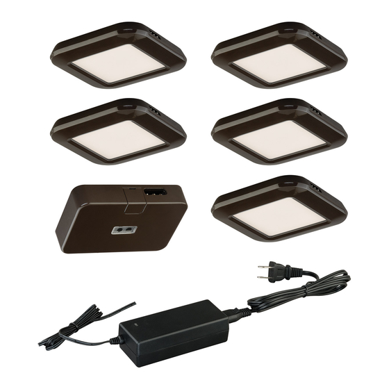
Hardware Package (included):
36W Driver (A)
Important to Know:
1. Read all instructions carefully before installation and operation. Save instructions for future reference.
2. If you are not familiar with national and local electrical codes, it is recommended that you consult with a qualified
electrician.
3. This product has a polarized plug (one blade is wider than the other) as a feature to reduce the risk of electric shock.
This plug will fit in a polarized outet only one way. If the plug does not fit fully in the outlet, reverse the plug. If it still
does not fit, contact a qualified electrician. Never use with an extension cord unless plug can be fully inserted . Do
not alter the plug.
3. Multiple fixtures can be linked in series: up to 10 puck lights from 1 power source.
4. Do not use in wet locations, use indoors only.
5. LEDs are non-replaceable. Do not attempt to open the light fixture.
6. LED light output is strong enough to cause eye damage. Avoid staring directly at the LED light source for prolonged
periods of time.
7. Specification:
Item #:
NO.
1
X0029
2
X0030
3
X0031
X0032
4
X0033
Bronze
5
Bronze
6
X0034
Installation Steps
Turn off the power at fuse or circuit box.
1. Carefully unpack the fixture. Lay out all parts on a clean surface.
2. Determine desired placement for mounting puck lights and control sensor unit. Be sure spacing of components does
not exceed maximum length of power cord (from outlet) and linking cables (from one component to the next). The
mounting surface should be a minimum of 0.5 inch thick.
INSTRUCTIONS
TO AVOID RISK OF ELECTRICAL SHOCK, BE SURE TO SHUT OFF
POWER WHILE INSTALLING OR SERVICING THIS FIXTURE.
12" Linking Cord (B)
Body
Details
color
White
3-pack Kit
White
5-pack Kit
White
7-pack Kit
3-pack Kit
Bronze
5-pack Kit
7-pack Kit
Mounting Screw (C)
Metal Disk (D)
Dimension(inch)
Total
Watts
A
B
C
9 W
3
1/2
3
3
15 W
3
1/2
3
1/2
3
21 W
9 W
3
1/2
3
3
3
1/2
15 W
3
3
1/2
21 W
Page 1 / 4
Long Double-
Wood Screw (E)
sided Tape
A
C
150414
Short Double-
sided Tape
B
Advertisement

Summary of Contents for Vaxcel X0029
- Page 1 ASSEMBLY AND INSTALLATION INSTRUCTIONS X0029 / X0030 / X0031 / X0032 / X0033 / X0034 WARNING: TO AVOID RISK OF ELECTRICAL SHOCK, BE SURE TO SHUT OFF POWER WHILE INSTALLING OR SERVICING THIS FIXTURE. NOTES: 1. Before installing, consult local electrical codes for wiring and grounding requirements.
- Page 2 Fig.1. Note 1: The recommended location for the undercabinet light fixture is near the front edge of the cabinet as shown in fig.1. This provides Cabinet the best light distribution across the countertop. Note 2: Sensor control unit can be connected at the beginning, middle, or end of a series.
- Page 3 14. Plug the connector into the sensor and plug the driver into a 120V AC 60HZ outlet. (See Fig. 8) Fig.8. Fig.7. 12" Linking Cord (B) Cable Clip 36W Driver (A) Metal Disk (D) Outlet Turn on the power at the main fuse or circuit breaker box. Linking multiple fixtures: Multiple light fixtures can be linked up to a single driver by using a mini connector or by using additional linking cords.
- Page 4 Marking of sensor position Label This hardware package contains an indicator label. You may stick the label on the cabinet in order to mark the position of the sensor if so desired. Sensor Cleaning This light fixture is made from quality materials that will last for many years with minimum care. When cleaning, make sure you have unplugged your fixture, and have allowed sufficient time for the unit to cool to room temperature.