Table of Contents
Advertisement
Advertisement
Chapters
Table of Contents

Related Manuals for Thales Cinterion LGA DevKit Series

Summary of Contents for Thales Cinterion LGA DevKit Series
- Page 1 ® Cinterion LGA DevKit User Guide Version: DocId: lga_devkit_ug_v03...
- Page 2 Copyright © 2020, THALES DIS AIS Deutschland GmbH Trademark Notice Thales, the Thales logo, are trademarks and service marks of Thales and are registered in certain coun- tries. Microsoft and Windows are either registered trademarks or trademarks of Microsoft Corporation in the United States and/or other countries.
-
Page 3: Table Of Contents
® Cinterion LGA DevKit User Guide Page 3 of 36 Contents Contents Introduction ......................... 5 Feature and Benefits..................5 Supported Products ................... 6 Package Content ....................7 Quickstart ........................9 Mounting the LGA DevKit Socket ..............9 LGA DevKit Overview ....................10 Top and Underside View.................. - Page 4 ® Cinterion LGA DevKit User Guide Page 4 of 36 Contents Document Information....................24 Revision History ....................24 Related Documents ..................24 Safety Precaution Notes .................. 25 Regulatory Compliance Information..............25 Appendix........................26 LGA DevKit SM....................26 9.1.1 Placement ................... 26 9.1.2 Schematics ..................
-
Page 5: Introduction
® Cinterion LGA DevKit User Guide Page 5 of 36 1 Introduction Introduction ® ® The Cinterion LGA DevKit is designed as a generic development adapter for Cinterion ® modules. With the LGA DevKit it is no longer necessary to connect the Cinterion evaluation modules to an adapter for test and development purposes. -
Page 6: Supported Products
® Cinterion LGA DevKit User Guide Page 6 of 36 1.2 Supported Products Supported Products The following table lists modules that are supported by the LGA DevKit variants SM and L, de- pending on the module’s pad count (i.e., module’s footprint). Table 1: Supported products LGA DevKit SM LGA DevKit L... -
Page 7: Package Content
® Cinterion LGA DevKit User Guide Page 7 of 36 1.3 Package Content Package Content The following packages are available for the LGA DevKits. Normally an LGA DevKit SM or L would be used with the LGA DevKit socket SML: ®... - Page 8 ® Cinterion LGA DevKit User Guide Page 8 of 36 1.3 Package Content Cinterion ® LGA DevKit socket SML (L30960-N0110-A100) Cinterion ® LGA DevKit L Cinterion LGA DevKit SM ® (L30960-N0112-A100) (L30960-N0111-A100) LGA120 LGA156 LGA106 LGA114 Figure 2: LGA DevKit socket SML with LGA DevKit variants SM and L lga_devkit_ug_v03 2020-05-29 Public / Released...
-
Page 9: Quickstart
® Cinterion LGA DevKit User Guide Page 9 of 36 2 Quickstart Quickstart Please complete the following steps to quickly get started with your LGA DevKit. • Mount the LGA DevKit socket onto the LGA DevKit (for details see Section 2.1). -
Page 10: Lga Devkit Overview
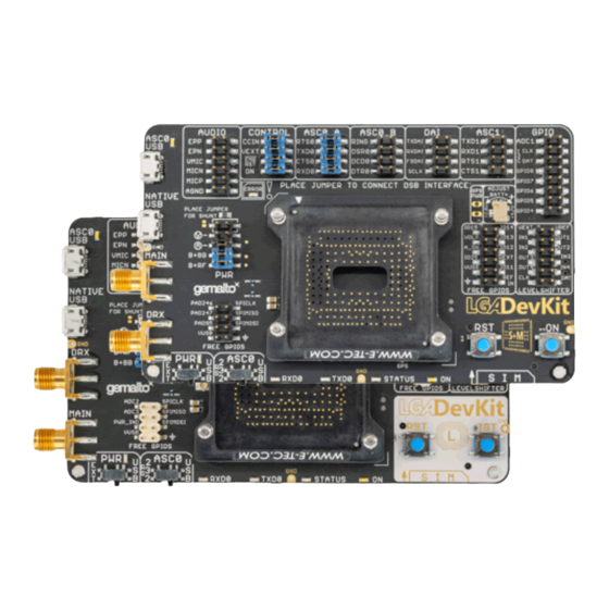
® Cinterion LGA DevKit User Guide Page 10 of 36 3 LGA DevKit Overview LGA DevKit Overview Top and Underside View Figure 3 Figure 4 show the top and underside view of the of the LGA DevKit SM variant. Please note that both SM and L variants of the LGA DevKit are identical - except or the MAIN and DIV antenna connectors that are interchanged, and the footprint indicators showing the dif- ferent LGA module footprints. -
Page 11: Block Diagram
® Cinterion LGA DevKit User Guide Page 11 of 36 3.2 Block Diagram Block Diagram Native Micro USB Data Left side: Right side: Module Pins Peripherals Combinded Powering Module Signals RF Main/ DRX On board ASC0 Micro GPS Antenna Connector Connector Connector Jumper Status LEDS GPS Signal Jumpers ASC0 Switch Signal FTDI ASC0 Auto Adjust Serial –... -
Page 12: Lga Devkit Interfaces
® Cinterion LGA DevKit User Guide Page 12 of 36 4 LGA DevKit Interfaces LGA DevKit Interfaces The LGA DevKit comes with two USB interfaces supporting power supply and serial commu- nication. You may choose to setup communication via a module's USB port and/or a module's UART (ASC0) port via FTDI232R VCP. -
Page 13: Pin Headers
® Cinterion LGA DevKit User Guide Page 13 of 36 4.3 Pin Headers Pin Headers The pin headers at the top side can be used to setup connections between modules and pos- sible on board peripherals. Thus, pin headers having signal names at their left side only, name- ly the pin headers AUDIO, CONTROL, ASC0_A, ASC0_B, DAI, ASC1, GPIO, and PWR, can be bridged by jumpers. -
Page 14: On Button: Module Start And Power Down
® Cinterion LGA DevKit User Guide Page 14 of 36 4.4 ON Button: Module Start and Power Down ON Button: Module Start and Power Down Pushing the ON button shortly (i.e., <0.5s), the LGA DevKit starts up and initially analyses the mounted module orientation and type. -
Page 15: Free Level Shifters
® Cinterion LGA DevKit User Guide Page 15 of 36 4.8 Free Level Shifters Free Level Shifters The LGA DevKit provides 8 free level shifters, with 4 placed & connected at the patch field on the underside, and 4 connected to the pin header "LEVELSHIFTER". The level shifters on the pin header are referenced to the module's Vext, and Vref that by default corresponds to 3V or to "REF IN"... -
Page 16: Rf Antenna
® Cinterion LGA DevKit User Guide Page 16 of 36 4.11 RF Antenna 4.11 RF Antenna The LGA DevKit supports three antenna interfaces. The two SMA connectors "MAIN" and "DRX" are used for radio transmission. The GNSS interface is supported by an U.FL connector named "GPS". -
Page 17: Power Supply
® Cinterion LGA DevKit User Guide Page 17 of 36 4.12 Power Supply 4.12 Power Supply The LGA DevKit can be supplied through one or two USB ports that should be in the range of 5V +-5%, and/or externally by the DSB75/DSB-Mini. The modules supply level can be adjusted in the range between 2.8…4.8V by setting the variable resistor at the DevKit's top side. -
Page 18: External Reference Supply
® Cinterion LGA DevKit User Guide Page 18 of 36 4.12 Power Supply 4.12.2 External Reference Supply To drive/operate the LGA DevKit's interfaces at certain voltage levels, an external reference voltage may be connected. By default, i.e., without an external reference voltage connected, the interface operates at 3V to meet the DSB75/DSB-Mini requirements. -
Page 19: General Characteristics
® Cinterion LGA DevKit User Guide Page 19 of 36 5 General Characteristics General Characteristics The following table lists absolute maximum ratings for the LGA DevKit. Please note that viola- tion of these limits may cause permanent damage to the LGA DevKit. Table 2: Absolute maximum ratings Parameter Unit... -
Page 20: Operating The Lga Devkit With A Dsb
® Cinterion LGA DevKit User Guide Page 20 of 36 6 Operating the LGA DevKit with a DSB Operating the LGA DevKit with a DSB LGA DevKit on DSB-Mini The LGA DevKit supports a 2x40pin connector at its underside, compatible to the DSB75/DSB- Mini. -
Page 21: Lga Devkit On Dsb75
® Cinterion LGA DevKit User Guide Page 21 of 36 6.2 LGA DevKit on DSB75 LGA DevKit on DSB75 To operate the LGA DevKit with the DSB75 please complete the following steps: • Mount the LGA DevKit onto the DSB75. •... -
Page 22: Module Specific Configuration Settings
® Cinterion LGA DevKit User Guide Page 22 of 36 7 Module Specific Configuration Settings Module Specific Configuration Settings The following sections describe specific settings that must be taken into account for certain modules. BGS1 and BGS2 Operation BGS2 requires a reference voltage for the I/O domain at VDIG (pad 10 of the LGA106 foot- print). -
Page 23: Ens22 Operation
® Cinterion LGA DevKit User Guide Page 23 of 36 7.4 ENS22 Operation ENS22 Operation To make sure that firmware updates are performed without interruption, the default jumper at "VEXT" at the "CONTROL" pin header must be removed. Instead, this jumper needs to be placed at the "LEVELSHIFTER"... -
Page 24: Document Information
Revised and updated document. document ® New document: "Cinterion LGA DevKit User Guide" v01 Chapter What is new Initial document setup. Related Documents Hardware Interface Description for your Thales module AT Command Set for your Thales module lga_devkit_ug_v03 2020-05-29 Public / Released... -
Page 25: Safety Precaution Notes
LGA DevKit. Failure to comply with these precautions violates safety stan- dards. Thales assumes no liability for customer’s failure to comply with these precautions. The following is a non-extensive list of the mobile phone and LGA DevKit usage restrictions: Pacemaker patients are advised to keep their hand-held mobile away from the pacemaker while it is on. -
Page 26: Appendix
® Cinterion LGA DevKit User Guide Page 26 of 36 9 Appendix Appendix LGA DevKit SM 9.1.1 Placement CON14 CON9 CON13 CON11 CON12 CON7 CON10 LED2 CON18 LED6 CON17 CON16 CON15 BTN1 BTN2 LED9 CON1 LED4 LED5 LED3 LED1 Top view R69 R70 IC18 IC17... -
Page 27: Schematics
® Cinterion LGA DevKit User Guide Page 27 of 36 9.1 LGA DevKit SM 9.1.2 Schematics MODULE1 SMA + U.FL CONNECTORS EHS5/6/8, ELS61, BGS2/5 Custom Dual Design EHS5/6/8, ELS61, BGS2/5 Custom Dual Design INDUSTRIAL FOOTPRINT U.FL-R-SMT(01)_np VUSB_MODULE 200R CON15 233/44 233/44 VUSB/[2] VUSB... - Page 28 ® Cinterion LGA DevKit User Guide Page 28 of 36 9.1 LGA DevKit SM TC1014-3.0VCT713 LDO BATT+ GPS PWR LDO +3V BATT+: 2.8V - 4.86V TP68 EXTERN_REFERENCE/[1] V480 VOUT BATT+/[1] T14A BATT+/[3] ISL80103 TP81 IC10 TP64 TP65 LDO_OUT/[3] EN_BATT+/[1] EN/UVLO NX3008PBKS DVDT ERROR_LED_OD...
-
Page 29: On_Module
® Cinterion LGA DevKit User Guide Page 29 of 36 9.1 LGA DevKit SM LEVEL SHIFTER ASC0.1 PINHEADER 80 PIN INTERFACE Control CON7 IC14 EEPROM VCC-B VREF/[2] VCC-A VEXT_BUFF/[2] ON/[1] ON_MODULE/[1] RXD0_X100/[2] RXD0@LS EMERG_RST_X100/[1] EMG_RST/[1] CTS0_X100/[2] CTS0@LS VEXT_JUMPER/[2] VEXT_MODULE/[1] CCIN_X100/[1] CCIN/[1] DAC_OUT_X100 DAC_OUT... -
Page 30: Lga Devkit L
® Cinterion LGA DevKit User Guide Page 30 of 36 9.2 LGA DevKit L LGA DevKit L 9.2.1 Placement CON11 CON14 CON7 CON9 CON10 CON13 CON12 LED2 CON18 LGA_MODULE LED6 CON17 C40 C41 C42 C43 CON1 LED9 C35C36 BTN1 BTN2 LED4 LED5 LED3... -
Page 31: Schematics
® Cinterion LGA DevKit User Guide Page 31 of 36 9.2 LGA DevKit L 9.2.2 Schematics LGA_MODULE SMA + U.FL CONNECTORS PATCHFIELD_BOTTOM PLS8/PHS8/AGS2/PDS8 Dual Design PLS8/PHS8/AGS2/PDS8 Dual Design 18pF 18pF VUSB_MODULE ANT_DRX 200R VUSB/[2] VUSB1 ANT_DRX_MIMO/ANT_DRX/DNU/NC ANT_DRX VUSB_MODULE VUSB1 BOARD.D+ USB_DP ANT_GNSS ANT_GPS... -
Page 32: Ldo Batt
® Cinterion LGA DevKit User Guide Page 32 of 36 9.2 LGA DevKit L TC1014-3.0VCT713 LDO BATT+ GPS PWR LDO +3V BATT+: 2.8V - 4.86V TP68 EXTERN_REFERENCE/[1] V480 BATT+ VOUT T14A BATT+ ISL80103 TP81 IC10 TP64 TP65 LDO_OUT/[3] EN_BATT+/[1] EN/UVLO NX3008PBKS DVDT ERROR_LED_OD... -
Page 33: Txd
® Cinterion LGA DevKit User Guide Page 33 of 36 9.2 LGA DevKit L LEVEL SHIFTER PINHEADER 80 PIN INTERFACE ASC0.1 CON7 Control IC14 VCC-A VCC-B VREF/[2] VEXT_BUFF/[2] IGT/[1] IGT_MODULE/[1] RXD0_X100/[2] RXD0@LS EMERG_RST_X100/[1] EMG_RST/[1] CTS0_X100/[2] CTS0@LS VEXT_JUMPER/[2] VEXT_MODULE/[1] DAC_OUT ADC1_IN CCIN_X100/[1] CCIN/[1] DAC_OUT_X100... -
Page 34: Errata/Troubleshooting
® Cinterion LGA DevKit User Guide Page 34 of 36 9.3 Errata/Troubleshooting Errata/Troubleshooting PCB22/23 with DSB-Mini as Expander Board - ON LED With the LGA DevKit version B22/23 - built in smaller quantities - a current back feeding causes a constantly glowing WHITE ON LED. There is no impact in functionality. PCB B22 Module Rotation Detecting Limited The LGA DevKit's PCB revision B22 - built in a smaller quantity - has a limited rotation detect- ing. -
Page 35: Lga_Devkit_Ug_V03
® Cinterion LGA DevKit User Guide Page 35 of 36 9.3 Errata/Troubleshooting The old LGA DevKit socket has a decreased RF matching that is improved with the new socket. The below Figure 20 Figure 21 shows measurements with the old LGA DevKit socket re- garding the S11 DevKit's MAIN antenna module RF path as well as the S21 DevKit's MAIN an- tenna RF path loss. - Page 36 THALES DIS AIS Deutschland GmbH Werinherstrasse 81 81541 Munich Germany...
Need help?
Do you have a question about the Cinterion LGA DevKit Series and is the answer not in the manual?
Questions and answers