LG ARNU09GQAA4 Installation Manual
Hide thumbs
Also See for ARNU09GQAA4:
- Svc manual (91 pages) ,
- Engineering product data book (521 pages)
Table of Contents
Advertisement
Quick Links
INSTALLATION MANUAL
AIR
CONDITIONER
Please read this installation manual completely before installing the product.
Installation work must be performed in accordance with the national wiring
standards by authorized personnel only.
Please retain this installation manual for future reference after reading it
thoroughly.
CONSOLE
Original instruction
[Representative] LG Electronics Inc. EU Representative : LG Electronics European Shared
Service Center B.V. Krijgsman 1, 1186 DM Amstelveen, The Netherlands
[Manufacturer] LG Electronics Inc. Changwon 2nd factory 84, Wanam-ro, Seongsan-gu,
Changwon-si, Gyeongsangnam-do, KOREA
MFL67798139
Rev.00_041619
Copyright © 2017 - 2019 LG Electronics Inc. All Rights Reserved.
www.lg.com
Advertisement
Table of Contents

Related Manuals for LG ARNU09GQAA4


Summary of Contents for LG ARNU09GQAA4
- Page 1 Please retain this installation manual for future reference after reading it thoroughly. CONSOLE Original instruction [Representative] LG Electronics Inc. EU Representative : LG Electronics European Shared Service Center B.V. Krijgsman 1, 1186 DM Amstelveen, The Netherlands [Manufacturer] LG Electronics Inc. Changwon 2nd factory 84, Wanam-ro, Seongsan-gu, Changwon-si, Gyeongsangnam-do, KOREA www.lg.com...
-
Page 2: Table Of Contents
Table of contents TABLE OF CONTENTS INSTALLATION PARTS SAFETY PRECAUTIONS INSTALLATION Selection of the Best Location Indoor unit installation Flaring Work Connecting the Piping Wiring Connection DIP Switch Setting Group Control Setting Model Designation Airborne Noise Emission Limiting concentration Indoor Unit... -
Page 3: Installation Parts
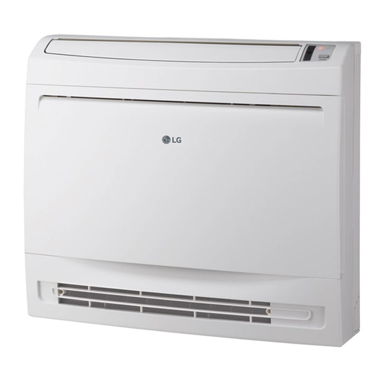
Installation Parts Installation Parts Air filter Signal receiver Operation lamp Air purifier lamp ON/OFF button Air outlet Air inlet Allergy filter Remote Controller (Accessory) Installation Clamp Name Drain Hose Other Plate (Tie wrap) Quantity 1 EA 1 EA 4 EA - Allergy Filter - Fixing screw for Installation Plate 4*25 mm - 5 EA... -
Page 4: Safety Precautions
Safety Precautions Safety Precautions The following symbols are displayed on indoor and outdoor units. Read the precautions in this manual This appliance is filled with flammable carefully before operating the unit. refrigerant (R32) This symbol indicates that a service This symbol indicates that the Operation personnel should be handling this Manual should be read carefully. - Page 5 Safety Precautions • Do not modify or extend the power cable. - There is risk of fire or electric shock. • Do not install, remove, or re-install the unit by yourself (customer). - There is risk of fire, electric shock, explosion, or injury. •...
- Page 6 Safety Precautions Operation • Do not let the air conditioner run for a long time when the humidity is very high and a door or a window is left open. - Moisture may condense and wet or damage furniture. • Take care to ensure that power cable could not be pulled out or damaged during operation.
- Page 7 Safety Precautions • Ventilate the product from time to time when operating it together with a stove, etc. - There is risk of fire or electric shock. • Turn the main power off when cleaning or maintaining the product. - There is risk of electric shock. •...
- Page 8 Safety Precautions • Do not install the product where it will be exposed to sea wind (salt spray) directly. - It may cause corrosion on the product. Corrosion, particularly on the condenser and evaporator fins, could cause product malfunction or inefficient operation.
- Page 9 Safety Precautions • Do not step on or put anything on the product. (outdoor units) - There is risk of personal injury and failure of product. • Always insert the filter securely. Clean the filter every two weeks or more often if necessary. - A dirty filter reduces the efficiency of the air conditioner and could cause product malfunction or damage.
-
Page 10: Installation
Installation Installation Read completely, then follow step by step. Selection of the Best Location • There should not be any heat source or steam near the unit. • There should not be any obstacles to the air circulation. • A place where air circulation in the room will be good. •... - Page 11 Installation Minimum floor area (for R32) - The appliance shall be installed, operated and stored in a room with a floor area larger than the minimum area. - Use the graph of table to determine the minimum area. Amin (m Floor standing Wall mounted Ceiling mounted...
-
Page 12: Indoor Unit Installation
Installation Indoor unit installation 1. Preparation / Removing front panel 1. Open the front grille by pulling forward 2. Then pull out the link of grille from groove in front panel. 3. Then pull out 2 hinges of grille from grooves in front panel. 4. - Page 13 Installation 3. Refrigerant Piping 1. The location of hole is different depending on which side of the pipe is taken out. 2. Drill a hole(Ø 70 mm) in the point indicated by symbol in the illustration as below. Wall Left bottom piping Right bottom piping Left back piping Right back piping...
- Page 14 Installation 4. Drill a Hole in the wall • Drill the piping hole with a Ø 7 0mm hole core drill. Drill the piping hole at either the right or the WALL left with the hole slightly slanted to the outdoor Indoor Outdoor side.
- Page 15 Installation 6. Installing Indoor unit 6-1 Installation on the Floor. 1. Fix up using 6 screws for floor installation. (700) 30.5 6 screw (M4*25L) 30.5 (Unit : mm) 6-2 Installation on the Wall 1. Fix up the installation plate using 5 screws and the indoor unit using 4 screws. 2.
- Page 16 Installation 6-3 Half concealed installation. 1. Make a wall hole of the size shown Fig-1. Wall Supplemental plate Supplemental plate (Field supply) (Field supply) Hole (Unit : mm) <Fig - 1> 1) Normal concealed 2) Deep concealed 2. Installation of supplemental plate for attaching main unit •...
- Page 17 Installation 3. Piping Hole Wall Left bottom piping Right bottom piping Left pipng Wall (Unit : mm) 4. Remove the Deco Covers and Fixing Indoor Unit 1) Remove the Deco Covers. 2) Insert the Indoor Unit to the Wall hole. 3) Secure using 6 screws.
-
Page 18: Flaring Work
Installation Flaring Work Main cause for gas leakage is due to defect of flaring work. Carry out correct flaring work in the following procedure. Cut the pipes and the cable. 1. Use the piping kit accessory or the pipes purchased Copper locally. -
Page 19: Connecting The Piping
Installation Connecting the Piping When you connect the refrigerant pipe, it is easier that you connect the gas pipe first. 1. Hold up the Sensor Link. 2. Separate the Pipe Bracket (2 screws) 3. Connect the refrigerant pipe. (Refer to next page) 4. - Page 20 CAUTION If the drain hose is routed inside the room insulate the hose with an insulation material* so that dripping from sweating (condensation) will not damage furniture Tape or floors. Connecting * Foamed polyethylene or equivalent is cable recommended. Drain hose Connecting pipe Connecting the installation pipe and drain hose to the indoor unit.
-
Page 21: Wiring Connection
Installation Wiring Connection • Connect the wires to the terminals on the control board individually according to the outdoor unit connection. • Ensure that the color of the wires of outdoor unit and the terminal No. are the same as those of indoor unit respectively. Terminal block of outdoor unit Central controller Outdoor unit Indoor unit... -
Page 22: Dip Switch Setting
Installation DIP Switch Setting Function Description Setting Off Setting On Default Communication N/A (Default) Cycle N/A (Default) Selection of Master or Slave Group Control Master Slave Dry Contact Mode Selection of Dry Contact Wired/Wireless remote Mode controller Auto Selection of Manual or Auto operation Mode Fan continuous operation Installation... - Page 23 Installation 2. Outdoor Unit In case that the products meet specific conditions, “Auto addressing” function can start automatically with the improved speed by turning the DIP switch #3 of the outdoor unit and resetting the power. * Specific conditions: - All names of the indoor units are ARNU****4. - The serial number of Multi V super IV (outdoor units) is after October 2013.
-
Page 24: Group Control Setting
Installation Group Control Setting 1. Group Control 1 n Wired remote controller 1 + Standard Indoor Units LGAP Network System Signal Master Slave Slave Slave 12 V Only connect serial signal and Display Error Message GND lines between indoor units. Master n DIP Switch in PCB ¿... - Page 25 Installation h It is possible to connect indoor units since Feb. 2009. h It can be the cause of malfuctions when there is no setting of master and slave. h In case of Group Control, it is possible to use following functions. - Selection of operation, stop or mode - Temperature setting and room temperature check - Current time change...
- Page 26 Installation 3. Group Control 3 n Mixture connection with indoor units and Fresh Air Intake Unit LGAP Network System Signal Master Slave Master Slave 12 V Display Error Message Display Error Message Master Master h In case of connecting with standard indoor unit and Fresh Air Intake Unit, separate Fresh Air Intake Unit with standard units.
- Page 27 Installation 4. 2 Remote Control n Wired remote controller 2 + Indoor unit 1 LGAP Network System Slave Slave Slave Signal Master 12 V Display Error Message Master Slave 1. It is possible to connect two wired remote controllers (Max.) with one indoor unit. Set only one indoor unit to Master, set the others to Slave.
- Page 28 Installation 5. Accessories for group control setting It is possible to set group control by using below accessories. Indoor unit 2 EA +Wired remote controller Indoor unit 1 EA +Wired remote controller 2 EA h PZCWRCG3 cable used for connection h PZCWRC2 cable used for connection Slave Master...
-
Page 29: Model Designation
Installation Model Designation Serial Number Combinations of functions A:Basic function L: Neo Plasma(Wall Mounted) C: Plasma(Ceiling Cassette) G: Low Static K: High Sensible Heat U: Floor Standing without Case SE/S8 - R: Mirror V: Silver B:Blue(ART COOL Type Panel Clolr) - E: Red V: Silver G:Gold 1: Kiss (Photo changeable) - Page 30 Indoor Unit...
Need help?
Do you have a question about the ARNU09GQAA4 and is the answer not in the manual?
Questions and answers