Table of Contents
Advertisement
Quick Links
CU-32
APRIL 5, 2013
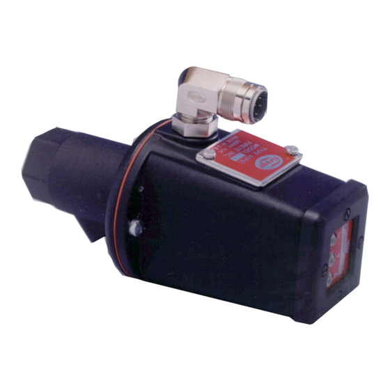
TYPE 45FS1/45UVFS1
MODEL 1000, 1001
FLAME
SIGNATURE
SCANNER™
DESCRIPTION
®
The FIREYE
Type 45FS1 and 45UVFS1 Signature Scanner™ flame detectors incorporate an inno-
vative flame detection method to determine the presence or absence of a target flame in a single or
multiple burner environment. Both scanners utilize a software algorithm that constantly compares
the amplitude-frequency characteristics of the target flame with the amplitude-frequency characteris-
tics that they learn during a setup procedure. This amplitude-frequency characteristic will be referred
to as the signature of the target flame. During the learn mode the scanner performs "real time" anal-
ysis of the frequency spectrum of the AC signal of the target flame to determine the type of flame
being sensed (e.g. burner flame-on, flame tips from adjacent burners, background flame, no flames,
etc.) and determines a specific shape or Flame Signature of the flame's frequency spectrum. When
the scanner is put in the run mode, the Signature Scanner controls constantly compare the targeted
flame signal with the learned signatures to determine the status of the flame.
The 45FS1/45UVFS1 then provides a pulsed output to indicate that the flame signal matches its
learned flame signature. This pulse output is analogous to the strength of the flame signal, allowing
the scanner to be compatible with the 25SU3 and 25SU5 style flame amplifiers.
The main difference between the 45FS1 and 45UVFS1 scanners is the flame detector utilized in each
scanner. The 45FS1 scanner incorporates a large area lead sulfide cell sensitive to the infra-red range
more suitable for coal and/or oil type flames. This cell can detect a wide range of background bright-
ness without experiencing cell washout. The 45UVFS1 scanner uses a super-blue silicon cell sensi-
tive to the UV range, as well as an automatic signal amplification circuitry making it applicable for
all fuel types (gas/oil/coal).
The Signature Scanner flame detectors have the ability for remote communication to review and
program the system setpoints as well as download and upload the "learned" flame signature data
from one scanner to another using an IBM compatible PC and the FS700 software program. Refer to
Bulletin CU-39 for details.
The 45FS1/45UVFS1 Scanners have an eight (8) character LED display, a three (3) pushbutton key-
pad, and a program enable pushbutton to program and/or review the various system setpoints and
operating parameters associated with the setup procedure and operation of the scanner. Flame signa-
tures can be learned for a number of fuel types (gas, oil, coal, etc.). The selection of the flame signa-
ture is determined via the keypad or the remote file selector switches.
1
Advertisement
Table of Contents

Related Manuals for Fireye FLAME SIGNATURE SCANNER 1000

Summary of Contents for Fireye FLAME SIGNATURE SCANNER 1000
- Page 1 SCANNER™ DESCRIPTION ® The FIREYE Type 45FS1 and 45UVFS1 Signature Scanner™ flame detectors incorporate an inno- vative flame detection method to determine the presence or absence of a target flame in a single or multiple burner environment. Both scanners utilize a software algorithm that constantly compares the amplitude-frequency characteristics of the target flame with the amplitude-frequency characteris- tics that they learn during a setup procedure.
-
Page 2: Operation
Flame Signature Scanner and the Programming Primer (CU-33). The 45FS1/45UVFS1 flame scanners are compatible with the following Flame Safeguard controls: — Fireye Type 25SU3, Model -2000, -2100, 4170, 4172, 5166, 5168, 5172, 5173 — Fireye Type 25SU5, Model 5011, 5012 (Refer to Figures 19, 20, and 21 for wiring diagrams). - Page 3 make the 45UVFS1 scanner a logical choice for coal (when burning combination of gas/oil or gas/ coal), oil, and gas burners. CAUTION: The only sure way to determine if a flame scanner will provide proper flame detection and discrimination for a particular fuel type and burner type is to set up and test the scanner under a number of varying operating conditions (e.g.
- Page 4 1 1/2 (38) TEXTURED FINISH PURGE AIR CONNECTION 1.57 (40) Optional Mounting Configurations for Hazardous Areas FIGURE 2. 45FS1/45UVFS1 SCANNER IN NEC/NEMA HAZARDOUS AREA HOUSING FIREYE FLAME SCANNER 16 3/16 (412.79) 1 1/4" NPT CONDUIT P/N 45FS1-1000EX (Includes Model ENTRY 8.25 (210) 45FS1-1000 Scanner) ±...
-
Page 5: Agency Approvals
Shipping Weight: 2.4 Lbs. (1.1 Kg) Electrical Power Requirements: +24 VDC from associated Fireye control or +24 VDC (+10%, - 15%) from an external power supply. Current rating: 100 mA per scanner. Connection: Quick disconnect. The male connector is assembled with the scanner housing. The female (cable connector) is ordered separately (P/N 129-127-6). -
Page 6: Installation Procedure
INSTALLATION CAUTION: Due to the micro-processor based design of the 45FS1/45UVFS1 scanner, the heat insulating nipple (P/N 35-127-1 or 35-127-3) must be used to insulate the scanner from ground and to reduce conducted energy and noise. Failure to do so could result in erratic operation of the scanner. - Page 7 FIGURE 5. SCANNER LOCATION VS. SECONDARY AIR ROTATION IGNITOR IGNITOR SCANNER SCANNER MAIN MAIN BURNER BURNER CCW ROTATION CCW ROTATION Having determined the approximate location for the sight pipe, cut a clearance hole for a 2 inch pipe through the burner plate. Look through the hole. If register vanes interfere with the desired line of sight, the interfering vane(s) should be trimmed to assure an unrestricted viewing path at all firing levels.
- Page 8 The scanner lens must be kept free of contaminants (oil, ash, soot, dirt) and the scanner temperature must not exceed its maximum rating of 150° F (65° C) for 45FS1 or 131°F (55°C) for 45UVFS1. Excessive temperatures will shorten scanner life. Both requirements will be satisfied by a continu- ous injection of purge air at either the 3/8”...
- Page 9 FIGURE 9. 13" (330) MAX* PART NUMBER A. SWIVEL MOUNT 60-1664-3 (NPT) 60-1664-4 (BSP) B. HEAT INSULATING NIPPLE 35-127-1 (NPT) 35-127-3 (BSP) C. 3/8” THREADED OPENING *NOTE: SCANNER SHOWN IN PHOTOGRAPH IS NOT A 45FS1 SIGNATURE SCANNER. FIGURE 10. PART NUMBER A.
-
Page 10: Electrical Accessories
The number of conductors required for wiring the 45FS1/45UVFS1 scanner to the associated ampli- fier is dependent on the functions utilized by the scanner. Fireye offers a six (6) conductor cable (P/N 59-470) that can be used for most applications. The 59-470 cable is made up of four (4) #18 AWG conductors and two (2) #22 AWG conductors. - Page 11 Eight (8) connectors are pre-wired to the female quick disconnect. The remaining twelve (12) connectors are used for wiring the Fireye 6 conductor cable (59-470) back to the flame amplifier (for +24 VDC Power, Shutter, Common, Flame Signal, Remote File Select 1 & 2), and multi-drop the 2 conductor Belden cable (22 AWG, #8761) between scanners.
- Page 12 61-6694 scanners. The male connector is factory mounted on the scanner. The female cable connec- tor kit, P/N 129-127-6, is ordered separately. This assembly procedure applies to Fireye six-conduc- tor cable (P/N 59-470), eight-conductor cables (P/N 59-471), and obsolete four-conductor cable (P/N 59-221).
- Page 13 Install the contacts into the female insert in the appropriate order. When properly installed, the contacts will “click” into the insert. Verify by pulling slightly on each wire. Place the threaded hood nut over the female insert. Slide the connector hood over the female insert, aligning the hood locating “key” with the wide groove on the female insert.
- Page 14 NOTE 5: OPTION #1: THE CORD GRIP STRAIN RELIEF CONTAINS A BUSHING SUITABLE FOR FIREYE 59-470 CABLE (0.375”- 0.438” O.D.). IF FIREYE 59-471 CABLE IS USED, SUBSTITUTE THE ALTERNATE BUSHING (0.500”- 0.562” O.D.). TORQUE TO 35 INCH POUNDS. Note: Refer to Figures 19, 20, and 21 for proper wiring of the scanner cable to the appropriate controls.
-
Page 15: Grounding And Shielding Techniques
GROUNDING AND SHIELDING TECHNIQUES FOR USE ON SCANNERS OR SCANNER CABLE LOCATED WITHIN 12" OF A HIGH ENERGY OR HIGH VOLTAGE SOURCE. The scanner and scanner cable (preferably within flexible conduit) MUST be located at least one foot (1') from the ignition source. Run a ground wire from the ignition transformer chassis to the ignitor assembly. - Page 16 For distances less than 200 feet, wire the Fireye cable 59-471 to the female quick disconnect in the following manner and run the cable directly back to the flame amplifier.
- Page 17 To provide remote communications without using the Fireye Wiring Harness, it is necessary to run the Fireye eight (8) conductor cable (59-471) a short distance from the scanner to a junction box. From the junction box, wire the Fireye 59-470 cable back to the appropriate amplifier. Then wire Belden 8761 (22 AWG, twisted shielded pair wire) between each junction box and finally back to the communication source to complete the “Multi-drop”...
- Page 18 FIGURE 17. WIRING FOR REMOTE FILE SELECT AND/OR REMOTE COMMUNICATIONS USING LOCAL ELECTRICAL JUNCTION BOX QUICK DISCONNECT PINS 59-471 OF 45FS1/45UVFS1 CONNECT SCANNER SHIELDS 1 BLACK + 24VDC TOGETHER AND GROUND AT +24VDC BLACK BLACK AMPLIFIER. WHITE WHITE COMMON COMMON 59-470 WHITE...
- Page 19 Flame amplifier rack, P/N 60-1706, has a blocking diode between terminals 14A and 14D. Tape the shield at the 45UV5, 45RM1, 45RM2 scanner end. Fireye recommends the use of shielded cable for the two remote file select switches (or relays). These controls should be rated for low current (3mA) operation.
- Page 20 The shield at the scanner end should be taped and isolated. Fireye recommends the use of shielded cable for the two remote file select switches (or relays). These controls should be rated for low current (3mA) operation.
- Page 21 FIGURE 21. WIRING TO 25SU3-2100 AMPLIFIER RACKS USING 59-470 OR 59-471 CABLE CONNECTOR TERMINALS FOR 60-2471-1 HALF RACK OR 60-2471-3 FULL RACK FEMALE QUICK DISCONNECT WIRING HARNESS AT 45FS1/45UVFS1 YELLOW RFS2 (OPTIONAL) BLUE RFS1 - (OPTIONAL) 25SU3-2100 (SHUTTER) BLACK (+24VDC) WHITE (COMMON)
- Page 22 A third selection for the setpoint RFS is COMM. With this selection, the file is selected via remote communication. Refer to Communications Address under Status menu. Fireye recommends the use of shielded cable for the two remote file select switches (or relays). These controls should be rated for low current (3mA) operation.
- Page 23 Status Menu MNEMONIC CODE DESCRIPTION ALLOWABLE VALUES Flame Off The status of the monitored flame. Flame On/Off FQ = 0 Flame quality 0-100 T = 43 C Internal flame scanner temperature XX = °F or XX = °C FILE =F Reference flame data file A, B, C, F, (:), (*) (See NOTE below)
-
Page 24: Status Menu
STATUS MENU LOOP (Except for temperature, all values shown are factory default setting) T=43C Keypad Legend FILE = F Advance (Advances menu) Help (Scrolls descriptor) FQ=0 Change (Not functional in status loop) DISCR = 9 START HERE FLAME = OFF COMM = 0 SCANNER MESSAGES... - Page 25 Discrimination (DISC) - Indication of the quality of discrimination obtained from the Learned Flame On and Learned Flame off profiles. This menu item is very useful. During the setup proce- dure, the user should try to maximize this value. Allowable values are 0 to 9. Value should be at least 5 or higher for discrimination to occur.
- Page 26 SETPOINT MENU LOOP (All values shown are factory default setting) STATUS MENU LOOP EDIT A RUN A EDIT N (NOTE 1) COMM = 0 ABORT FFRT = 3 BFRT = 3 OTD = 2 ADVANCE KEY REQUIRED TO TEMP = C SCROLL THROUGH F = GAS B = OFF...
-
Page 27: Mnemonic Code
SETPOINT MENU LOOP (continued) MNEMONIC CODE DESCRIPTION ALLOWABLE VALUES EDIT N Edit a file Yes, No (Note 1) EDIT A Select the file to edit A, B, C, F COMM = 0 Communication Address 0 - 127 FFRT = 3 Flame failure response time 1-6 seconds BFRT = 3... - Page 28 Type of Amplifier (AMP) - This selects the type of amplifier the scanner will be used with. Selec- tions are: 5000 - Fireye Type 25SU3/25SU5, Series 5000 (e.g.: -5172, -5173, -5011, -5012, -5166). R900 - Detector Electronics, Type R900/R910. 2000 - Fireye Type 25SU3, Series 2000.
- Page 29 conditions (e.g.: Flame On = 10, Flame Off = 40, difference = 30). The lower the value, the stronger the flame signal. During Flame On, a lower number is desirable; during Flame Off, a higher number is desirable. This setpoint also calculates the automatic gain adjustment. See Setup Procedure. Note: This setpoint is not programmable.
- Page 30 PROGRAMMING ERRORS TO WATCH FOR When programming the 45FS1/45UVFS1 scanners, there are several programming sequences that can cause apparent discrimination problems to the user. They are: Never use the AIM or LEARN FLAME ON NEW setpoints when the target flame is Off. The setpoint LEARN FLAME ON NEW erases any “Flame On and Flame Off”...
-
Page 31: Troubleshooting
TROUBLESHOOTING The 45FS1/45UVFS1 flame scanner contains certain diagnostic information helpful in troubleshoot- ing the scanner. In the event of a problem where you need to contact the factory, please perform the following steps. Press the Program Enable key to enter Setpoints Menu. Press the Advance key (➡) until the Setpoint AIM is displayed. - Page 32 Fireye warranty, as stated it its General Terms and Conditions of Sale, pertains only to the Fireye products and not to any other equipment or to the combined system or its overall performance.
Need help?
Do you have a question about the FLAME SIGNATURE SCANNER 1000 and is the answer not in the manual?
Questions and answers