Advertisement
2562227B
REV. B 1006
Printed in U.S.A
SAFETY MESSAGE TO INSTALLERS AND USERS
People's lives depend on your safe installa-
tion of our products. It is important to read,
under- stand, and follow all instructions
shipped with the products. In addition, listed
below are some other important safety in-
structions and precautions you should follow:
•
To properly install lightbar, you must
have a good understanding of automo-
tive systems, along with proficiency in
the installation and use of safety warning
equipment.
•
DO NOT install equipment or route wir-
ing in the deployment path of an air bag.
•
This product contains high intensity LED
devices. To prevent permanent eye dam-
age, DO NOT stare into the light beam at
close range.
•
A light system is a high current device. In
order for it to function properly, a sepa-
rate ground connection must be made. If
practical, it should be connected to the
negative battery terminal. At a minimum,
it may be attached to a solid metal body
or chassis part that will provide an effec-
tive ground path as long as the light sys-
tem is used.
•
When drilling into a vehicle structure, be
sure both side of the surface are clear of
anything that could be damaged.
•
Locate the light system controls so the
VEHICLE and CONTROLS can be oper-
ated safely under all driving conditions.
•
The mounting system should be periodi-
cally inspected to ensure that it is secure-
ly attached to the vehicle.
•
File these instructions in a safe place and
refer to them when maintaining and/or
reinstalling the product.
Failure to follow all safety precautions and
instructions may result in property damage, serious
injury, or death to you or others.
INSTALLATION AND MAINTENANCE INSTRUCTIONS FOR
HEAVY-DUTY RAYDIAN® LED LIGHTBAR
I.
GENERAL.
HEAVY OBJECT
Get assistance when lifting or installing.
Failure to do so will cause permanent bodily
injury.
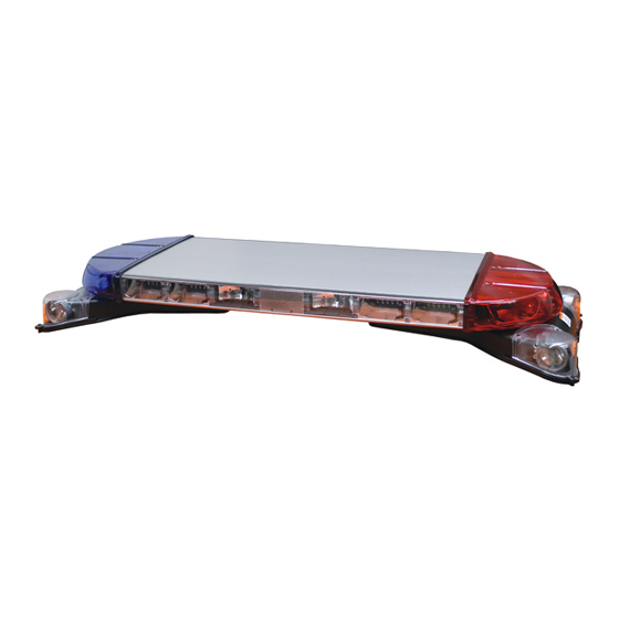
The Raydian is a LED light bar, with supplemental
white halogen area lighting, designed for use with Federal
Signal lightbar controllers and/or single switches rated
at 2-amperes and above. The base is a two piece extruded
aluminum profile with polycarbonate lenses and end
domes. The unit is supplied with mounting hardware and
a thirty-foot cable, and has an operating temperature of
–40oC to +65oC.
II.
UNPACKING.
After unpacking the Raydian light assembly, inspect it
for damage that may have occurred in transit. If the unit
has been damaged, do not attempt to install or operate
it. File a claim immediately with the carrier, stating
the extent of the damage. Carefully check all envelopes,
shipping labels, and tags before removing or destroying
them.
III. INSTALLATION.
A. General.
Before proceeding, ensure that the lightbar has
been installed on the vehicle roof in accordance with the
instructions packed with the mounting kit. The lightbar is
completely wired at the factory and does not require any
additional internal wiring. All the conductors necessary
for control of any and all basic and optional functions are
contained in the cables. The basic light functions of the unit
must be controlled by a user-supplied control head.
Light system controls must be located so the
VEHICLE and CONTROLS can be operated
safely under all driving conditions.
1. Route the control cable into the vehicle and
near the eventual location of the user-supplied control
head. Route the Red 10 gauge power wire into the vehicle
and to the battery.
2. For proper light operation, the control cable
must be properly terminated inside the user-supplied
control head. Using figure 1 as a guide, make the
Advertisement
Table of Contents

Related Manuals for Federal Signal Corporation RAYDIAN


Summary of Contents for Federal Signal Corporation RAYDIAN
- Page 1 2562227B REV. B 1006 Printed in U.S.A INSTALLATION AND MAINTENANCE INSTRUCTIONS FOR HEAVY-DUTY RAYDIAN® LED LIGHTBAR SAFETY MESSAGE TO INSTALLERS AND USERS GENERAL. HEAVY OBJECT People’s lives depend on your safe installa- Get assistance when lifting or installing. tion of our products. It is important to read,...
- Page 2 2. Front-light Cut Off. CONTROL CABLE Applying 12VDC to the front-light cut off (-) BATTERY (GREEN) wire will cause the front of the lightbar to cut off. (+) BATTERY MODE 1 When the front-light cut off is active, only the rear and rear ORANGE MODE 2 portion of the end cap will function. YELLOW MODE 3 GREEN FRONT LIGHT CUT-OFF 3. Rear-light Cut Off. GREY REAR LIGHT CUT-OFF Applying 12VDC to the rear-light cut off BROWN WORKLIGHTS (GREY) wire will cause the rear of the lightbar to cut off. VIOLET LEFT ALLEY When the rear-light cut off is active, only the front and BLUE RIGHT ALLEY front portion of the end cap will function.
- Page 3 Mode 2 (Tow Mode) b. Momentarily apply 12VDC to the 1 - Alternate Double Flash D1, D4, D6, D8, P1, P4, P6, Program (PINK) wire. The lightbar will stop briefly, then P8 with D2, D3, D5, D7, P2, P3, P5, P7 with A the entire lightbar LEDs will flash the number of the new Center Out SignalMaster. flash pattern. The lightbar will then begin to flash the 2 - Alternate Double Flash D1, D4, D6, D8, P1, P4, P6, newly selected pattern. P8 with a Single Flash Of D2, D3, D5, D7, P2, P3, P5, P7 with A Signalmaster Pattern Of S1, S2, Repeat step b until the desired pattern is S7, S8 Alternating with S3, S4, S5, S6. selected. 3 - The Lightbar is split into 4 Quadrants: A, B, C, & D and are flashed as follows: A, C, B, D, A, C, B, d. To program the other modes, apply D…...Each block is Single Flashed at 50ms per 12VDC to the desire mode input and repeat steps b and c. Flash. 4 - Double Quadrant Flash, followed by a full lightbar C. Function Activiation – SignalMaster. Quad Flash, followed by a single Quadrant Flash. 5 - Quad Flash – Wrap-Around Inside to Outside 1. SignalMaster Center-Out (Warn) – Followed by a full lightbar Quad Flash. 6 – Wrap-Around Inside to Outside – 30ms Per Head. Applying 12VDC to the SignalMaster Center- 7 - Alternate Full Flash followed by Tow Mode Pattern out (BLACK) wire will cause the SignalMaster lights to illuminate from the Center-out.
- Page 4 CENTER ARROW: (Default Center Arrow Pattern is 1) D. SignalMaster Control Head Installation. 1 - Solid Center Arrow – 250mS between flashes 2 - Double Center Arrow – 250mS between flashes 3 - Single Center Arrow – 250mS between flashes 4 - Solid Center Arrow – 200mS between flashes When installing equipment inside air bag 5 - Double Center Arrow – 200mS between flashes equipped vehicles, the installer MUST ensure 6 - Single Center Arrow – 200mS between flashes that the equipment is installed ONLY in areas 7 - Solid Center Arrow – 150mS between flashes recommended by the vehicles manufacturer. 8 - Double Center Arrow – 150mS between flashes 9 - Single Center Arrow – 150mS between flashes Failure to observe this warning will reduce 10-Solid Center Arrow – 100mS between flashes the effectiveness of the air bag, damage the...
-
Page 5: Safety Message To Operators
E. Electrical Connections. Ensure that there are no loose wire strands or other bare wires which may cause a short circuit. Also, all wires must be protected from any sharp edges which could eventually cut through the insulation. Failure to observe this WARNING may result d. Connect the 18-gauge red wire to the in fire, burns, or blindness. positive (+) terminal of the battery using an in-line user- supplied fuseholder and 25A fuse. Locate the fuse as near If shorted to vehicle frame, high current con- the battery as possible to protect the entire length of wire. ductors can cause hazardous sparks resulting in electrical fires or molten metal IV. -
Page 6: Maintenance
MAINTENANCE. Crazing (cracking) of lenses will cause reduced ef- fectiveness of the light. Do not use cleaning agents (which will cause crazing) such as strong deter- gents, solvents, or petroleum products. If crazing of lenses does occur, reliability of light for emergency signaling purposes may be reduced until lenses are replaced. TOP VIEW HOLLOW “O” RING CORD High voltages are present inside the lightbar. Wait LENS at least 10 minutes after shutting off the power before servicing the unit. Disconnect ALL power to the lightbar before any maintenance is performed. Failure to do so may result in property damage, SOLID “O” RING CORD serious injury, or death to you or others. END VIEW 290A5636B Figure 5. After prolonged operation, The unit gets hot and connector. With the end dome removed from the bar, can cause burns. Do not touch the unit while or remove the 10-32 Phillips head screw from the bottom of shortly after it has been operating. Always allow the dome. The lighting units, upper plate, and lower plate the unit to cool before handling. are now removed from the dome as an assembly. Once free of the dome, the top plate and lighting units lift free from A. General. the lower plate. - Page 7 D. Halogen Lamp Replacement. REFLECTOR PCB ASSEMBLY A serious injury may result if the lamp is touched when hot. Always allow lamp to cool before removing. Halogen lamps are pressur- ized and if broken can result in flying glass. Always wear gloves and eye protection when handling lamps.
-
Page 8: Replacement Parts
8654180 6 Button Solaris LED Assemblies PCB Assembly, Backer Board 2005340 P.C.B. BOARD AND PCB Assembly, STT, Backer Board 2005314 BRACKET ASSEMBLY Reflector Assembly, 6 Button Amber 8654167-02 Reflector Assy., Stop/Tail/Turn, Red 8654207 1/4-20 HEX LED, 6 Button, Amber 8625234-A HEAD SCREW LED, STT, Red 2005303A 1/4" FLAT WASHER Copyright 2006 Federal Signal Corporation 1/4" LOCKWASHER 290A5639 Figure 8.
Need help?
Do you have a question about the RAYDIAN and is the answer not in the manual?
Questions and answers