Table of Contents
Advertisement
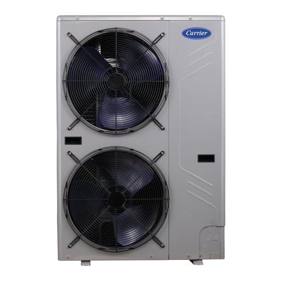
Single-Phase Variable Refrigerant Flow (VRF) Heat Pump Systems
Installation and Maintenance Instructions
CONTENTS
SAFETY CONSIDERATIONS . . . . . . . . . . . . . . . . . . . 1
GENERAL . . . . . . . . . . . . . . . . . . . . . . . . . . . . . . . . . . . 2
INSTALLATION . . . . . . . . . . . . . . . . . . . . . . . . . . . . . . . 4
Step 1 - Unpack and Inspect Units . . . . . . . . . . . . 4
Step 2 - Position the Unit . . . . . . . . . . . . . . . . . . . . 4
Step 5 - Adjust Refrigerant Charge . . . . . . . . . . . . . 8
Step 6 - Complete Electrical Connections. . . . . . . . 8
START-UP . . . . . . . . . . . . . . . . . . . . . . . . . . . . . . . . . . 13
Trial Run. . . . . . . . . . . . . . . . . . . . . . . . . . . . . . . . . . . . 13
Error Codes. . . . . . . . . . . . . . . . . . . . . . . . . . . . . . . . . 13
Unit Settings . . . . . . . . . . . . . . . . . . . . . . . . . . . . . . . . 14
Pre-Start Check . . . . . . . . . . . . . . . . . . . . . . . . . . . . . 15
MAINTENANCE . . . . . . . . . . . . . . . . . . . . . . . . . . . 15
Manufacturer reserves the right to discontinue, or change at any time, specifications or designs without notice and without incurring obligations.
Catalog No. 20-38VMH002-01
Page
Printed in U.S.A.
Form 38VMH-1P-2SI
SAFETY CONSIDERATIONS
Improper
installation,
adjustment,
maintenance, or use can cause explosion, fire, electrical shock,
or other conditions, which may cause death, personal injury or
property damage. The qualified installer or agency must use
factory-authorized kits or accessories when modifying this
product.
Follow all safety codes. Wear safety glasses, protective
clothing, and work gloves. Use quenching cloth for brazing
operations. Have fire extinguisher available. Read these
instructions thoroughly and follow all warnings or cautions
included in literature and attached to the unit. Consult local
building codes and the current editions of the National
Electrical Code (NEC) ANSI/NFPA (American National
Standards Institute/National Fire Protection Association) 70. In
Canada, refer to the current editions of the Canadian Electrical
Code CSA (Canadian Standards Association) C22.1.
Understand the signal words - DANGER, WARNING, and
CAUTION. DANGER identifies the most serious hazards,
which will result in severe personal injury or death.
WARNING signifies hazards that could result in personal
injury or death. CAUTION is used to identify unsafe practices,
which would result in minor personal injury or product and
property damage.
Recognize safety information. This is the safety-alert
symbol (
). When this symbol is displayed on the unit and in
instructions or manuals, be alert to the potential for personal
injury. Installing, starting up, and servicing equipment can be
hazardous due to system pressure, electrical components, and
equipment location.
WARNING
Electrical shock can cause personal injury and death. Shut
off all power to this equipment during installation. There
may be more than one disconnect switch. Tag all
disconnect locations to alert others not to restore power
until work is completed.
Pg 1
01-20
38VMH036-060
Outdoor Unit for
alteration,
service,
Replaces: 38VMH-1P-1SI
Advertisement
Table of Contents

Subscribe to Our Youtube Channel
Related Manuals for Carrier 38VMH Series


Summary of Contents for Carrier 38VMH Series
-
Page 1: Table Of Contents
38VMH036-060 Outdoor Unit for Single-Phase Variable Refrigerant Flow (VRF) Heat Pump Systems Installation and Maintenance Instructions CONTENTS SAFETY CONSIDERATIONS Page Improper installation, adjustment, alteration, service, SAFETY CONSIDERATIONS ....1 maintenance, or use can cause explosion, fire, electrical shock, GENERAL . -
Page 2: General
WARNING CAUTION When installing the equipment in a small space, provide DO NOT re-use compressor oil or any oil that has been adequate measures to avoid refrigerant concentration exposed to the atmosphere. Dispose of oil per local codes exceeding safety limits due to refrigerant leak. In case of and regulations. - Page 3 Table 2 — 38VMH Physical Data UNIT NOMINAL TONS (Ton) POWER SUPPLY (V-Ph-Hz)* 208/230-1-60 COOLING CAPACITY WITH NON-DUCTED & DUCTED INDOOR UNITS† Nominal (kBtu/h) Rated (kBtu/h) HEATING CAPACITY WITH NON-DUCTED & DUCTED INDOOR UNITS† Nominal (kBtu/h) 52.5 Rated (kBtu/h) 52.5 ELECTRICAL CHARACTERISTICS WITH NON-DUCTED INDOOR UNITS Power Consumption (kW) 3.10...
-
Page 4: Installation
After determining the condition of the unit exterior, carefully remove the packaging and inspect for hidden damage. Check to make sure that items (thermostats, controllers, etc.) are accounted for whether packaged separately or shipped at a later date. Any hidden damage should be recorded, a claim should be filed with the transportation company, and the factory should be notified. -
Page 5: Step 3 - Connect Refrigerant Piping And Wiring
NOTE: All dimensions shown in inches. Fig. 3 — Single Unit Installation Fig. 5 — Lifting the Unit CONCRETE BASE REQUIREMENTS • The unit’s base must be made of solid concrete. • Ensure that the base is level and that the weight of the unit is distributed evenly. - Page 6 PIPING CONNECTIONS BETWEEN OUTDOOR AND REFRIGERANT PIPING MEASUREMENTS INDOOR UNITS Table 3 — Main Pipe Sizing CAUTION MAIN PIPE SIZE CAPACITY 38VMH UNIT SUCTION SIDE LIQUID SIDE (tons) During brazing, keep nitrogen in pipes to avoid oxidation (in.) (in.) inside the pipes. Use soapy water or refrigerant leak detector to verify every joint in the refrigeration piping.
- Page 7 Figures 10 and 11 and Tables 6 and 7 show allowable piping lengths and elevation differentials when connecting the outdoor units to indoor units. Fig. 10 — Piping Lengths and Drop Height Table 6 — Permitted Pipe Lengths and Drop Heights DESCRIPTION ALLOWABLE VALUE (ft) PIPES...
-
Page 8: Step 4 - Pressure And Vacuum Test System
Step 4 — Pressure and Vacuum Test If the total calculated amount of refrigerant cannot be added to the system, close the valve on the refrigerant bottle, move the System — After completing the refrigerant piping, perform charging house from the liquid line service port to the suction the following pressure test: line service port. - Page 9 Fig. 14 — Typical Wiring Diagram...
- Page 10 POWER SUPPLY — Electrical characteristics POWER WIRING — Installation of wiring must conform available power supply must agree with the unit nameplate with local codes and with NEC ANSI/NFPA 70, current rating. Circuit breaker size and supply voltage must be as edition.
- Page 11 820 feet between the wired controller and indoor units. Communication wires are sold separately but can be obtained through Carrier. Figure 18 below shows a typical communication wire from Carrier.
- Page 12 Outdoor Unit Centralized controller NOTE: 24 v. AC Power HA HB Indoor unit 1# Indoor unit 2# Indoor unit 3# Indoor unit 4# wired controller NOTE: Power from IDU HA HB Indoor unit 5# Maximum wiring length L1+L3< 3937 ft 18AWG, 2-Core Stranded Shield L5 <...
-
Page 13: Start-Up
START-UP OPTION/EXTENSIONS OF COMMUNICATION WIRING — To extend control wiring or make terminal Trial Run — Set a different address for each indoor unit. connections, use the PQE connection wire supplied in the Addresses can range from 0 to 63. Address can be set accessory kit and follow the steps below. -
Page 14: Unit Settings
Unit Settings Table 11: SW3 and SW4 Function Definition SW3 Function Definition SW4 Function Definition Heating priority mode Automatic addressing Cooling priority mode Non-automatic addressing (factory default) First running priority mode Clear IDU address Heating mode only Fahrenheit temperature (factory default) Cooling mode only Celsius temperature Table 12: ENC1 and ENC2... -
Page 15: Pre-Start Check
Pre-Start Check MAINTENANCE • Check that the refrigerant pipe line and communication CAUTION wire with indoor and outdoor units have been connected to the same refrigeration system. When servicing or repairing this unit, use only factory- • Outdoor units require 208/230-1-60 power. Verify that approved service replacement parts. - Page 16 © Carrier Corporation 2020 Manufacturer reserves the right to discontinue, or change at any time, specifications or designs without notice and without incurring obligations. Catalog No. 20-38VMH002-01 Printed in U.S.A. Form 38VMH-1P-2SI Pg 16 01-20 Replaces: 38VMH-1P-1SI...
Need help?
Do you have a question about the 38VMH Series and is the answer not in the manual?
Questions and answers