Table of Contents
Advertisement
Quick Links
Niederworth 1–10
58579 Schalksmühle
Telefon
(0 23 55) 82-0
Telefax
(0 23 55) 82-105
www.rutenbeck.de
mail@rutenbeck.de
Allgemeines
line21 ® -Komponenten nutzen vorhandene
analoge Telefonleitungen für folgende
Anwendungen
• zusätzliche Vernetzung von
Datenendgeräten
• Nachrüstung von xDSL- oder Netzwerk-
anwendungen
• Ausweitung von Netzwerk- und xDSL-
Anwendungen.
Installation des PPR 6 in einer
Unterverteilung
1 Legen Sie das fachgerecht vorbereitete
Kabel in die Klemme ein
und schrauben Sie die
Kabelschelle fest.
2 Legen Sie die Adern ent-
sprechend Bild 5 an den
Anschlussklemmen an.
3 Drücken Sie die Drähte
mit einem LSA-Anlege-
werkzeug in die Klemmen.
4 Nach Aufsetzen und
Befestigen des Deckels
stecken Sie die Patchka-
bel in die RJ45-Buchsen
an der Frontseite und stel-
len Sie die Verbindungen
zu den aktiven Netzwerk-
komponenten her (z. B.
Switch, s. Bild 1).
5 Zum Lösen der Patch-
kabel aus den Buchsen
drücken Sie zunächst auf
den Entriegelungsknopf
oberhalb der entspre-
chenden Buchse und
ziehen dann den Stecker
heraus (s. Bild 2).
Zubehör/Accessory
Switch SRM 5
Bild/fig. 1
Bild/fig. 2
235 105 01
line21 ®
Installationsanleitung
Installation instructions
General
line21 ® -components use the existing
analog telephone lines for the following
applications:
• Additional networking of data equipment
• Refitting of xDSL or network applications
• Expansion of network- and xDSL-
applications
Installation of PPR 6 in an electrical
distribution box
1 Lay the prepared pro-
fessionally cable in the
terminal of strain relief and
screw the cable clamp up.
2 Apply the cores to the
connecting terminals
according to figure 5.
3 Press the wires in the ter-
minals by using a suitable
tool, e.g. the connection
tool AW2.
4 Plug the patch panel in the
RJ45 jacks on the front
face and connect them
with the active network
components (s. fig. 1).
5 For the disconnection of
the patch panel from the
terminals press the release
knob above of the respec-
tive terminal at first and
then extract the plug from
the terminal (s. fig. 2).
Patchkabel PK0,23 m
Line Port Tester LPT
235 102 02
235 102 09
Advertisement
Table of Contents

Related Manuals for Rutenbeck Line21

Summary of Contents for Rutenbeck Line21
- Page 1 ® mail@rutenbeck.de Installationsanleitung Installation instructions Allgemeines General line21 ® -Komponenten nutzen vorhandene line21 ® -components use the existing analoge Telefonleitungen für folgende analog telephone lines for the following Anwendungen applications: • zusätzliche Vernetzung von • Additional networking of data equipment Datenendgeräten...
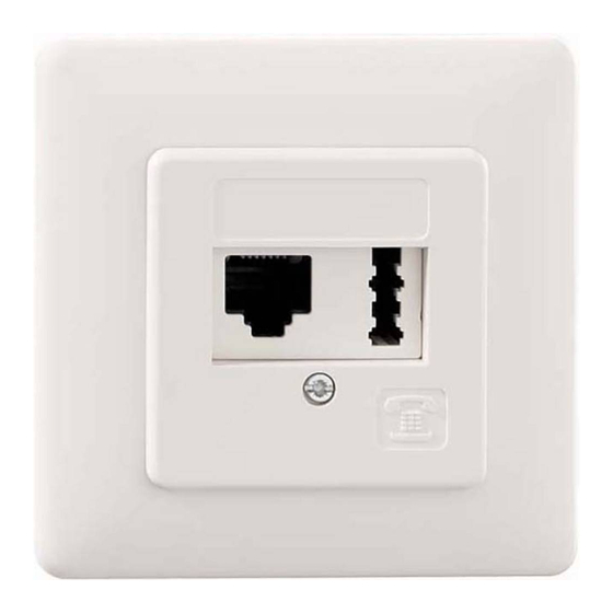
- Page 2 Installation/Installations Beschaltung der UAE 8/8 line21 ® / Terminal assignement UAE 8/8 line21 ® Klemmen-Nr. Adernfarbe* Adernpaar Funktion terminal color* pair function rot/ line21® schwarz/ line21® black weiß/ line21® white gelb/ line21® yellow rot/ analoge Telefonleitung ankommend**/ unten/bottom analog telephone line incoming**...
- Page 3 Anschlussseite line21®/ connection side line21® max. 50 m analoge Telefonleitung ankommend/ analog telephone line incoming Digitale Daten 10/100 MBit/s (DSL o. ä.)/ Digital data 10/100 MBit/s (DSL or the like) analoge Telefonleitung ankommend alternativ zur Buchse/ analog telephone line incoming alternatively to outlet Bild/fig.
- Page 4 Nach der Installation stecken Sie den After installation put the lid on and screw it Deckel wieder auf und schrauben Sie ihn fest. Die Kombination einer line21 ® - The combination of a line21 ® - Hinweis Notice Strecke mit ISDN-Anwendungen installation with ISDN-applications (S 0 ) ist nicht möglich.
Need help?
Do you have a question about the Line21 and is the answer not in the manual?
Questions and answers