Table of Contents
Advertisement
Advertisement
Table of Contents
Troubleshooting

Related Manuals for Chicago Pneumatic CPG 20


Summary of Contents for Chicago Pneumatic CPG 20
- Page 1 Instruction Manual for CPG Generators English CPG 20-25 Kd...
- Page 3 CPG 20-25 Kd Instruction Manual for CPG Generators Instruction manual ................5 Circuit diagrams ................42 Printed matter Nr 1310 3012 47 CHICAGO PNEUMATIC - PORTABLE AIR DIVISION www.cp.com 05/2011...
- Page 4 Neglecting maintenance or making changes to the setup of the machine can result in major hazards, including fire risk. While every effort has been made to ensure that the information in this manual is correct, Chicago Pneumatic does not assume responsibility for possible errors.
-
Page 5: Table Of Contents
While every effort has been made to ensure that the information in this manual is correct, Chicago Pneumatic does not assume responsibility for possible errors. Chicago Pneumatic reserves the right to make changes without prior notice. -
Page 6: Safety Precautions For Portable Generators
Skill level 3: Electrical technician The policy of Chicago Pneumatic is to provide the users manufacturer’s approval in writing. An electrical technician is trained and has the same... - Page 7 Safety during transport and installation 8 All regulating and safety devices shall be maintained 6 To lift heavy parts, a hoist of ample capacity, tested with due care to ensure that they function properly. and approved according to local safety regulations, To lift a unit, all loose or pivoting parts, e.g.
- Page 8 5 Never refill fuel while the unit is running, unless composition of the noise shall be provided and a otherwise stated in the Chicago Pneumatic Instruction special warning to that effect shall be placed at each Book (AIB). Keep fuel away from hot parts such as 20 Do not open electrical cabinets, cubicles or other entrance.
- Page 9 2 Parts shall only be replaced by genuine Chicago Pneumatic replacement parts. 13 Use only lubricating oils and greases recommended or approved by Chicago Pneumatic or the machine 3 All maintenance work, other than routine attention, manufacturer. Ascertain that the selected lubricants shall only be undertaken when the unit is stopped.
- Page 10 Tool applications safety Apply the proper tool for each job. With the knowledge of correct tool use and knowing the limitations of tools, along with some common sense, many accidents can be prevented. Special service tools are available for specific jobs and should be used when recommended.
-
Page 11: Leading Particulars
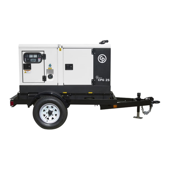
The CPG 20 and CPG 25 are CPG generators, built for continuous running at sites where no electricity is available or as stand-by in cases of interruption of the mains. The generator is equipped with a voltage selector switch which allows operation at 60 Hz, 480V L-L (277V L-N) 3PH, 240V L-L (139V L-N) 3 PH or 240V L-L (120V L-N) 1PH. The CPG 20 and CPG 25 generators are driven by a fluid-cooled diesel engine, manufactured by KUBOTA. - Page 12 Alternator Air filter Battery switch (optional equipment) Coupling Drain flexible engine oil DFW Drain flexible coolant Drain and access hole (in the frame) Drain plug fuel Engine FCW Filler cap coolant Filler cap engine oil Fuel filter Battery Oil filter Engine oil level dipstick - 12 -...
-
Page 13: Bodywork
Bodywork Drain plugs and filler caps Indicates the drain for the coolant. The alternator, the engine, the cooling system, etc. are The drain holes for the engine oil, the coolant and the plug enclosed in a sound-insulated bodywork that can be for the fuel, are located and labelled on the frame;... -
Page 14: Control And Indicator Panel Qc1002
Control and indicator panel Qc1002™ Qc1002™ Module Following LEDs are used on the Qc1002™ General description Qc1002™ control panel Power Qc 1002 Alarm Remote The Qc1002™ module is located inside the control panel. Power Green LED indicates that the unit is powered up. This control module will carry out all necessary tasks to Remote Green LED indicates that the Remote Mode is... - Page 15 Qc1002™ Menu Overview Alarm list display This view shows the Battery voltage and the running hours. At Qc1002™, the LCD will show following information: – in Normal condition (scroll through the information using Alarm List Fuel level display UP and DOWN): 0 Alarm(s) •...
- Page 16 EXTENDED STOP – Unit Type – Generator Overfrequency: failclass, enable, delay, TIMER setpoint Unit type 1 for CPG 20-25 ! – Generator Undervoltage: failclass, enable, delay, setpoint – Service Timer 2 reset COOLDOWN – Generator Overvoltage: failclass, enable, delay, setpoint It's possible to scroll between configuration menu's by –...
- Page 17 Alarm Display (pop-up window) List of possible alarms: SERVICE TIMER 2 LOW OIL PRESSURE ENGINE ALARM In case an Alarm occurs, a pop-up window will HIGH COOLANT automatically be displayed for as long as the alarm is TEMPERATURE active, no matter which view is active. The flashing red alarm LED will light up.
- Page 18 LOG list – running alarm, only supervision when the machine is running (RUN). The unit will keep an event log of the latest 30 events. Events are: – shutdowns – service timer 1/2 reset – unit type changes Together with each event, the running hours at the time of the event will be stored.
-
Page 19: Output Terminal Board
(30 mA) or the overcurrent protection (CPG 20: 32 A, CPG 25: 32 A) is activated or when the shunt trip is energized. It must be reset manually after eliminating the problem. -
Page 20: Operating Instructions
In your own interest, always strictly – The generator should be kept with the doors closed, in Consult Chicago Pneumatic for measures against the observe all relevant safety instructions. order to avoid the ingress of water and dust. Dust ingress adverse influence of non-linear loads. -
Page 21: Before Starting
Protection – Check that fuse F10 has not tripped and that the emergency stop is in the OUT position. Wire section Max. current (A) For safety reasons, it is necessary to provide ² Multiple core Single core H07 RN-F – Check that the load is switched off. an isolating switch or circuit breaker in each load circuit. - Page 22 Operating Qc1002™ – Check, by means of the generator gauges, that the voltage between the phases is identical and that the rated current Starting Qc1002™ in the third phase (L3) is not exceeded. – When single-phase loads are connected to the generator To start up the unit locally, proceed as output terminals, keep all loads well-balanced.
-
Page 23: Maintenance
1310 3004 23 For the most important subassemblies, Chicago Pneumatic has developed service kits that combine all wear parts. These service kits offer you the benefits of genuine parts, save on administration costs and are offered at reduced price, compared to the loose components. Refer to the parts list for more information on the contents of the service kits. - Page 24 Generators in standby application have to be tested on a regular basis. At least once a month the engine should run for Inspection by Chicago Pneumatic Service technician minimum 30 minutes at a high load (50% - 70%) that the engine reaches its operating temperature.
-
Page 25: Engine Maintenance
Engine maintenance Specifications GENOIL GENOIL 15W40 GENOIL from Chicago Pneumatic is the ONLY oil tested Refer to the engine’s operator manual for full Synthetic engine oil GENOIL 15W40 and approved for use in all engines built into Chicago maintenance, including instructions for changing the oil GENOIL 15W40 is a Synthetic ultra high Pneumatic compressors and generators. - Page 26 Chicago Pneumatic compressors and generators. Chicago Pneumatic's PARCOOL EG extended life coolant is the new range of organic coolants purpose designed to meet the needs of modern engines. PARCOOL EG can help prevent leaks caused by corrosion.
-
Page 27: Coolant Check
The quality of the product can be determined by three is reached. Turn off the engine and allow to cool. parameters. – A refractometer can be ordered from Chicago Pneumatic – Recheck coolant level and add if necessary. with part number 2913 0028 00. -
Page 28: Storage Of The Generator
Storage of the generator Checks and trouble shooting Never perform a test run with connected Storage power cables. Never touch an electrical connector without a voltage check. – Store the generator in a dry, frost-free room which is well When a failure occurs, always report what ventilated. -
Page 29: Alternator Troubleshooting
Alternator troubleshooting Symptom Possible cause Corrective action Alternator gives 0 Volt Blown fuse. Replace fuse. No residual voltage. Excite the alternator by applying a 12V battery voltage with a 30 W resistor in series on the + and - terminals of the electronic regulator, respecting the polarities. After being excited the alternator still gives 0 Volt. -
Page 30: Engine Trouble Shooting
Engine trouble shooting The table below gives an overview of the possible engine – Restriction in exhaust pipe. – Restriction in exhaust pipe. problems and their possible causes. – Engine temperature is too high. – Engine temperature is too low. –... - Page 31 Vibration – Fault in atomisers or atomisers of an incorrect type. – Restricted movement of engine speed control. – Engine temperature is too high. – Fan damaged. – Fault in engine mounting or flywheel housing. The pressure of the lubricating oil is too high –...
-
Page 32: Options Available For Cpg 20 And Cpg
The engine control circuit diagrams and the power circuit Engine coolant heater Automatic battery charger diagrams for the standard CPG 20 and CPG 25 units: To make sure that the engine can start and accept load The LED on the front indicated the battery's state of... - Page 33 View outside To maintain the Trailer – Check the tightness of the towbar bolts, the axle bolts and Position 1: Indicates that the fuel supply line to the wheel nuts at least twice a year and after the initial 50 the engine is connected to the internal fuel tank.
-
Page 34: Technical Specifications
Technical specifications Technical specifications for CPG 20 Kubota Readings on gauges Gauge Reading Unit Ammeter L3 (P3) Below max. rating Voltmeter (P4) Below max. rating Settings of switches Switch Function Activates at Engine oil pressure Shut down 0.5 bar Engine coolant temperature Shut down 105°C... - Page 35 Technical specifications for CPG 20 Kubota Fuel consumption at no load (0%) 1.3 kg/h Fuel consumption at 50% load 3.2 kg/h Fuel consumption at 75% load 4.1 kg/h Fuel consumption at full load (100%) 4.6 kg/h Specific fuel consumption (at full load, 100%) 0.254 kg/kWh...
- Page 36 Technical specifications for CPG 20 Kubota Electical system 12 Vdc Emission compliance Power circuit Circuit-breaker, 1-ph. (optional) Number of poles Thermal release It (thermal release is higher at 25°C) 80 A Magnetic release Im 3..5xIn Unit Dimensions (LxWxH) 2097.1 x 950 x 1141 mm...
-
Page 37: Technical Specifications For Cpg 25 Kubota
Technical specifications for CPG 25 Kubota Readings on gauges Gauge Reading Unit Ammeter L3 (P3) Below max. rating Voltmeter (P4) Below max. rating Settings of switches Switch Function Activates at Engine oil pressure Shut down 0.5 bar Engine coolant temperature Shut down 105°C Specifications of the engine/alternator/unit... - Page 38 Technical specifications for CPG 25 Kubota Frequency droop < 5% isochronous Fuel consumption at no load (0%) 1.3 kg/h Fuel consumption at 50% load 3.2 kg/h Fuel consumption at 75% load 4.1 kg/h Fuel consumption at full load (100%) 4.6 kg/h Specific fuel consumption (at full load, 100%) 0.254 kg/kWh Fuel autonomy at full load with standard tank...
- Page 39 Technical specifications for CPG 25 Kubota Speed governing electronic Capacity of oil sump Capacity of cooling system Electrical system 12 Vdc Emission compliance Power circuit Circuit-breaker, 3-ph. Number of poles Thermal release It (thermal release is higher at 25°C) 32 A Magnetic release Im 3..5xIn Circuit-breaker, 3-ph., lower voltage...
-
Page 40: Conversion List Of Si Units Into British Units
Derating Temperature Height (°C) 1000 1500 2000 2500 3000 3500 Conversion list of SI units into British Dataplate units 1 bar 14.504 psi 0.035 oz 1 kg 2.205 lb 1 km/h 0.621 mile/h 1 kW 1.341 hp (UK and US) 0.264 US gal 0.220 lmp gal (UK) 0.035 cu.ft... - Page 41 Circuit diagrams - 41 -...
- Page 42 1310 3200 08/00 Applicable for CPG 20-25 Compact - Controller circuit Qc1002™ - 42 -...
- Page 43 F1-F2 Fuses 4 A Alternator Automatic voltage regulator Earth leakage relay (O) IT-relay (O) Circuit breaker Circuit breaker 32 A (O) Circuit breaker 16 A/30 mA (O) Coolant heater (O) Voltage adjustment 1 k (O) Emergency stop (S2a: see Controller circuit) 50/60 Hz switch (O) E.L.R.
- Page 44 1310 3200 08/00 Applicable for CPG 20-25 Compact - Engine circuit - 44 -...
- Page 45 Generator Control Unit (set A1 in UNIT-type 1) Fuel level sensor Speed sensor Preheat resistor Fuse 10A DC Battery 12 Vdc Charging alternator Panel Light Starter solenoid Preheat relay Starter Relay Starter motor Fuel feed pump Engine Controller Unit A-meter V-meter Battery Switch (opt) Emergency Stop...
- Page 46 1310 3200 03/03 Applicable for CPG 20-25 Compact - Power circuit - 46 -...
- Page 47 F1..5 Fuse 4A Alternator Aux. relay (lower volt.) Aux. relay (higher volt.) Contactor Automatic Voltage Regulator Optional Equipment Q1.1 Circuit breaker 3pole Q1.2 Circuit breaker 3pole Circuit breaker 1 pole Circuit breaker 1 pole Circuit breaker 2pole Circuit breaker 2pole Coolant Heater Voltage Adjustment Potmeter Emergency stop (S2a see Engine Circ.)
- Page 48 1310 6000 26/01 Applicable for CPG 20-25 Compact - Power circuit - Single phase F1-F2 Fuses 4 A Alternator Automatic voltage regulator Earth leakage relay (opt)) Circuit breaker Coolant heater (opt)) Voltage adjustment 1K (opt) Emergency stop (S2a see Controller circuit)
- Page 50 www.cp.com...
Need help?
Do you have a question about the CPG 20 and is the answer not in the manual?
Questions and answers