Advertisement
Available languages
Available languages
Table of Contents
Advertisement
Table of Contents

Summary of Contents for Audiotec Fischer Match DSP
- Page 1 Digitaler 6-Kanal Signalprozessor Digital 6-channel signal processor...
-
Page 2: Herzlichen Glückwunsch
Verarbeitung und eine MATCH-Signalprozessors. überzeugende Anwendung ausgereifter Technolo- gien aus. Audiotec Fischer setzt mit dem MATCH DSP neue Maßstäbe im Bereich der Signalprozessortechnik. Viel Freude an diesem Produkt wünscht Ihnen das Dabei profitieren Sie als Kunde direkt von unserer Team von über 30-jährigen Erfahrung in der Forschung und... -
Page 3: Anschluss- Und Bedienelemente
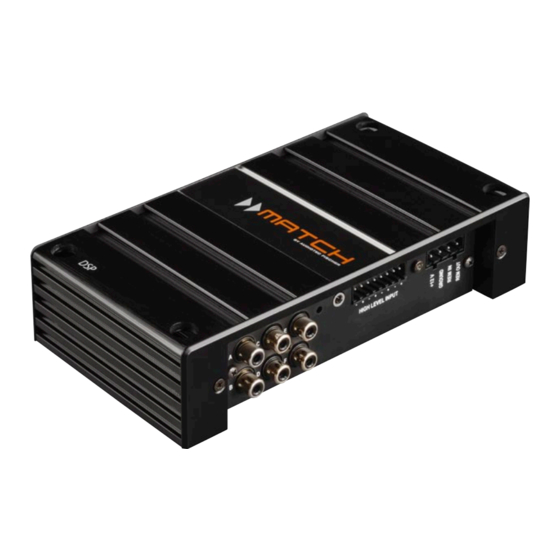
Anschluss- und Bedienelemente High Level Input Line Output Hochpegel-Lautsprechereingang zum An- Vorverstärkerausgänge zum Anschluss des/ schluss von Werksradios oder Radios ohne der Verstärker/s. Die maximale Ausgangs- Vorverstärkerausgänge. Über einen optio- spannung beträgt 4 Volt. nalen RCA-Cinch-Adapter kann dieser Ein- gang auch als Line Input verwendet werden. Gain Drehregler zum Anheben der Eingangsemp- Power Input... -
Page 4: Line Output
Die Status LED zeigt das aktuell ausgewählte auf den Highlevel Input um. Über das DSP-PC Tool Setup des MATCH DSP an. Leuchtet die LED grün, lassen sich im „Device Configuration Menu“ die Pa- ist Setup 1 (af1 / ac1) geladen. Bei Setup 2 (af2 / rameter des AUX-Eingangs verändern. -
Page 5: Control Input
9 USB Eingang durch einmaliges rotes Blinken der Status LED an- gezeigt. Mit Hilfe dieses Eingangs wird der MATCH DSP Wird der Taster länger als 5 Sekunden gedrückt, über das beiliegende Kabel mit dem Computer ver- so wird das Gerät resettet und der gesamte interne bunden und kann anschließend über das PC-Tool... - Page 6 RCA- / Cinch-Adapter der Batterie verbunden ist. Die Stromaufnahme auch als Lowlevel-Eingänge zum Anschluss des MATCH DSP ist mit weniger als 500 mA an die Vorverstärker- / Lowlevel- / Cinch- zwar sehr gering, trotzdem sollten Kabel mit Ausgänge des Radios verwendet werden.
- Page 7 DSP auch mit Hilfe des Easy Plug Kabels - EPC 5.2 ist die Leitung, an der auch bei ausgeschalteter (optional bei „MATCH DSP“ und im Paket „MATCH Zündung eine Spannung von 12V messbar ist. Ver- DSP incl. EPC 5.2“ enthalten) - angeschlossen wer- binden Sie nach erfolgter Messung das rote Kabel, den.
-
Page 8: Anschluss An Den Computer
USB-Kabel an den Computer DSP Kanäle separat eingestellt werden. anschließen. Verlängern Sie das Kabel auf kei- Bevor Sie den MATCH DSP das erste Mal an ei- nen Fall mit einer passiven USB-Verlängerung, nen Computer anschließen, gehen Sie auf unsere... - Page 9 Spezielle Features des MATCH DSP Power Save Modus Start-Stopfähigkeit Der Power Save Modus ist in der Grundeinstellung Das Netzteil im MATCH DSP stellt die interne Span- implementiert. Er erlaubt es, die Leistungsaufnah- nungsversorgung auch bei kurzfristigen Einbrüchen me der an den Prozessor angeschlossenen Ver- der Spannungsversorgung bis hinab zu 6 Volt si- stärker drastisch zu reduzieren, wenn für länger...
-
Page 10: Technische Daten
Technische Daten Eingänge .................4 x Hochpegel-Lautsprechereingang 1 x AUX Stereo Klinke 3,5 mm 1 x Remote In Eingangsempfindlichkeit ..........Hochpegel 10 Volt RMS Cinch 2,5 Volt (nur über optionalen RCA-/Cinch- Adapter) AUX 100 mV Eingangsimpedanz ............Hochpegel 30 Ohm komplexe Last RCA-/Cinch 14 kOhm Ausgänge ...............6 x Cinch 1 x Remote Out Ausgangsspannung ............4 Volt RMS... -
Page 11: General Instructions
DSP processor To prevent damage to the unit and possible injury, The MATCH DSP may only be installed in vehi- read this manual carefully and follow all installat- cles which have a negative ground electrical sys- ion instructions. This product has been checked for tem. - Page 12 Use this button to either switch between the Multifunction interface for e.g. the optional re- setups or initiate a reset of the device. mote control URC 2A or other MATCH DSP accessory. MicroSD card reader Will be used for uploading DSP setup files.
-
Page 13: Aux Input
Status LED. has to be removed. Attention: After erasing the setups from memory Attention: Solely use the pluggable screw-terminal the MATCH DSP will not reproduce any audio out- for the highlevel connector that comes with the de- put. vice! -
Page 14: Usb Input
Initial start-up and functions 9 USB Input tings. The setup file is copied automatically to the MATCH DSP when the card is inserted. Copying Connect your personal computer to the MATCH is shown by the Status LED blinking red; when it DSP using the provided USB cable. -
Page 15: Installation
Installation The MATCH DSP must be connected to the The jumper has to be removed by pulling it head unit (radio) as follows: straight upwards: Caution: Carrying out the following steps will re- quire special tools and technical knowledge. In or-... - Page 16 12 Volts wires may be reversed depending on vehicle type. The MATCH DSP should not be plugged into the po- wer supply via the ignition cable as this may cause interference. Before connecting the EPC 5.2 to the...
- Page 17 Caution: We strongly recommend to not connect any external amplifiers to the pre-amplifier outputs 1. Download the DSP PC-Tool software from the of MATCH DSP before you have done all the ba- website www.audiotec-fischer.com sic setup of the processor. Ignoring this advice may 2.
- Page 18 6 Volts during engine the MATCH DSP once there’s no input signal pre- crank. sent for more than 60 seconds.
-
Page 19: Technical Data
Technical Data Inputs ................4 x Highlevel speaker input 1 x AUX stereo phone jack 3.5 mm 1 x Remote in Input sensitivity ...............Highlevel 10 Volts RMS Lowlevel 2.5 Volts RMS (only usable with RCA/ Cinch adaptor) AUX 100 mV Outputs ................6 x Cinch 1 x Remote out Output voltage ..............4 Volts RMS Frequency response ............10 Hz - 22,000 Hz... - Page 20 Audiotec Fischer GmbH Gewerbegebiet Lake II · Hünegräben 26 · D-57392 Schmallenberg Tel.: +49 2972 9788 0 · Fax: +49 2972 9788 88 E-mail: match@audiotec-fischer.com · Internet: www.audiotec-fischer.com...


Need help?
Do you have a question about the Match DSP and is the answer not in the manual?
Questions and answers