Sign In
Upload
Download
Table of Contents
Contents
Add to my manuals
Delete from my manuals
Share
URL of this page:
HTML Link:
Bookmark this page
Add
Manual will be automatically added to "My Manuals"
Print this page
×
Bookmark added
×
Added to my manuals
Manuals
Brands
Absen Manuals
Industrial Monitor
AW Series
User manual
Absen AW Series User Manual
Hide thumbs
Also See for AW Series
:
User manual
(25 pages)
1
2
Table Of Contents
3
4
5
6
7
8
9
10
11
12
13
14
15
16
17
18
19
20
21
22
23
24
25
26
page
of
26
Go
/
26
Contents
Table of Contents
Bookmarks
Table of Contents
Table of Contents
1 Safety Information
2 Preparation before Installation
Site Installation Environment Preparation
Preparation of Maintenance Tools
3 Product Description
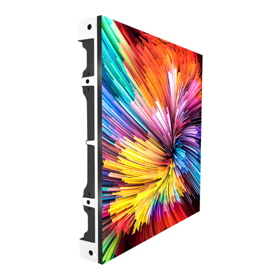
Pictures of Panels
Product Specifications
Pictures of Module
Pictures of Power
Pictures of Receiving Card
Distribution Box
Packing
4 Installation Procedure
Installation Notes
Front-Installation
5 Cable Connection
Load Quantity of Main Power Cable and Main Network Cable
Post-Installation Inspection
Turn on the Screen and See the Performance
For Software Operation, Please Refer to the Software Instruction Manual
6 Product Maintenance
Module Replacement
Common Installation Problems
7 Common Installation Issues
Large Gap between the Panels
The Panel Cannot be Fixed on the Square Tube (Frame)
Mask Lifting and LED Lamp Knocking out
8 Common Faults and Troubleshooting
Advertisement
Quick Links
1
Site Installation Environment Preparation
2
Pictures of Panels
3
Product Specifications
4
Pictures of Module
5
Installation Notes
Download this manual
AW Series User Manual
AW
Series User Manual
Table of
Contents
Previous
Page
Next
Page
1
2
3
4
5
Advertisement
Table of Contents
Need help?
Do you have a question about the AW Series and is the answer not in the manual?
Ask a question
Questions and answers
Related Manuals for Absen AW Series
Digital Signage Absen AW Series User Manual
(25 pages)
Industrial Monitor Absen AW2.8 User Manual
(26 pages)
Industrial Monitor Absen AW3.9 User Manual
(26 pages)
This manual is also suitable for:
Aw2.8
Aw3.9
Table of Contents
Save PDF
Print
Rename the bookmark
Delete bookmark?
Delete from my manuals?
Login
Sign In
OR
Sign in with Facebook
Sign in with Google
Upload manual
Upload from disk
Upload from URL


Need help?
Do you have a question about the AW Series and is the answer not in the manual?
Questions and answers