Table of Contents
Advertisement
Quick Links
KAPower Starting Module
KSM & MKSM Models
INSTALLATION – OPERATION MANUAL
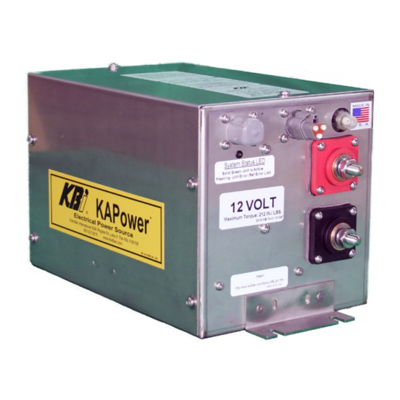
Gen 3 (12 Volts or 24 Volts)
KBI/Kold-Ban International, Ltd.
8390 Pingree Road, Lake In The Hills, Illinois 60156-9637 U.S.A.
(800) 527-8278, (847) 658-8561, Fax (847) 658-9280, www.koldban.com
ATA VMRS - T44 KLDBN
KBI® KAPower® © 2020 KBI Form #131480
Advertisement
Table of Contents

Summary of Contents for KBi KSM
- Page 1 Gen 3 (12 Volts or 24 Volts) KBI/Kold-Ban International, Ltd. 8390 Pingree Road, Lake In The Hills, Illinois 60156-9637 U.S.A. (800) 527-8278, (847) 658-8561, Fax (847) 658-9280, www.koldban.com ATA VMRS - T44 KLDBN KBI® KAPower® © 2020 KBI Form #131480...
- Page 2 CAUTION indicates a hazardous situation which, if not avoided, could result in equipment damage and/or equipment failure. KBI/Kold-Ban International, Ltd. accepts no responsibility or liability for any of its products that are improperly used. The safety information in this manual is provided as a guide for the user, and is not a substitute for proper training and usage.
-
Page 3: Table Of Contents
Figure 1: Parts List Items ................................4 Figure 2: Typical Cable Installations........................... 10 Figure 3: Six (6) Cell KSM ................................ 11 Figure 4: Ten (10) and Twelve (12) Cell KSM ......................... 12 Figure 5: General Wiring Installation ..........................14 Figure 6: Standard KSM Schematic ............................. 16 Figure 7: Standard MKSM Schematic.......................... -
Page 4: Parts List
PARTS LIST KSM Enclosure (See Figure 1) Double Pole Single Throw (DPST) switch (See Figure 1) Wiring harness (Not Shown) Terminal grease (Not Shown) Protective boots (Not Shown) 2.0 ITEMS NEEDED FOR INSTALLATION Battery cables (See Section 4.1 for cable recommendations) Terminals for battery cable Torque wrench with ¾... -
Page 5: Introduction
INTRODUCTION The KSM enclosure houses a KAPower module, contactor, PLC Module (Programable Logic Controller), circuit breaker, cables, conductors, and connectors. The cover of the KSM enclosure can be removed by unscrewing and removing the ten (10) fasteners found on the top and sides of the enclosure. -
Page 6: Kapower Advantages
The KAPower Module The KAPower module, which is housed within the KSM enclosure, represents an internal bank of 6, 10, or 12 capacitor cells series-connected to each other. Electrochemical Double-Layer Capacitor (EDLC) An Electrochemical Double-Layer Capacitor represents a device capable of storing and delivering electric power. - Page 7 34.5 lb. WARNING The KAPower KSM is a product of high electric power. Avoid shorting module terminals. A brief short circuit will not cause product failure, however, it may result in burning or igniting of combustible materials adjacent to the point of short circuit.
-
Page 8: Electrical Cable Selection
When selecting a location for installation, make sure that the KAPower KSM module will clear any lids and other movable parts. Install the KAPower KSM module as close to the engine's starting batteries or starter as possible. Avoid locations that are subject to extreme heat, humidity, dripping water (under deck ventilation systems aboard boats, for example), road dirt, ice, and snow. -
Page 9: Mounting The Ksm Unit
Avoid locations that are subject to extreme heat, dripping water, humidity, road dirt, ice, and snow. While the KSM unit may be mounted in any position or orientation, do not mount it directly over batteries, or under ventilation systems through which water might drip. - Page 10 Figure 2: Typical Cable Installations...
- Page 11 Figure 3: Six (6) Cell KSM...
- Page 12 Figure 4: Ten (10) and Twelve (12) Cell KSM...
-
Page 13: General Wiring Installation Procedure
General Wiring Installation Procedure Theory of Operation, Explaining how the KSM Module Works: Once installed and wired properly, the LED on the end-faceplate of the KSM will be illuminated green whenever the KSM contactor relay is closed. When the LED is illuminated, the contactor is closed;... - Page 14 NOTE: The J1939 connector is used for KBI factory programming only. Contact KBI for details. Figure 5: General Wiring Installation...
- Page 15 Wiring is complete and the unit is now ready to operate. WARNING After the installation and wiring are complete, and whenever the DPST switch is depressed, the KSM positive (+) and negative (–) terminals will be live. Do not short-circuit the terminals.
- Page 16 Figure 6: Standard KSM Schematic NOTE: In Transit bus applications where the rear-start feature is desired, a second DPST Switch can be installed in the rear-start location, wired in parallel with the front DPST switch.
- Page 17 Figure 7: Standard MKSM Schematic...
-
Page 18: Operation
Turn the vehicle/vessel key switch to the ON position, then push and hold down the DPST switch to engage the KAPower KSM system until the engine starts. By using power from the KAPower capacitor, the KSM contactor will close and stay closed whenever the DPST switch is depressed. The DPST switch is designed to engage the vehicle, vessel, or equipment’s OEM cranking motor circuit. -
Page 19: Troubleshooting And Maintenance
PLC (sourced from the engine ignition switched when ON) wiring harness you created. 2. This LED is also an indicator for how the KSM is functioning. The LED is connected in parallel with the contactor, and is also connected to an output on the PLC as shown in the Figure 6 and Figure 7. -
Page 20: To Check Ksm Internal Circuit
Check the circuit breaker and contactor relay connections within the KSM module. In order to service or replace any of these components, remove the cover of the KSM enclosure, with the assistance of KBI. The PLC Module is a sealed unit. It cannot be serviced. If additional troubleshooting... -
Page 21: Storage
The required storage temperature range is -76º to 185ºF (-60º to 85ºC). TRANSPORTATION The KAPower KSM modules can be shipped in approved corrugated cardboard, wooden, or plastic containers. For more information on transportation, contact KBI. -
Page 22: Appendix A: Supplement For Boats Using A Key-Switch For Single Engine Starting
NOTE: The following appendix is an alternate method for installations on vessels with key- switch starting. When installing KSM on a boat that incorporates key switch starting, no rocker switch or push button is required. NOTE: If the OEM engine manufacturer or the boat builder reviews the KBI KSM Theory of... - Page 23 Figure A1: Typical Cable Installations...
- Page 24 The PLC inside the KSM needs power at pin four from a source, such as the key-switch, that provides power only when the boat is in operation. See Figure A2. Example of existing key-switch. Figure A2: Typical Boat Key-Switch Schematic NOTE: “S”...
- Page 25 Figure A3: Schematic, Alternate Source for Start Signal...
-
Page 26: Appendix B: Supplement For Boats Using A Push Button Or Rocker Switch For Engine Starting (Including Boats With Multiple Engines)
The capacitor, the KSM circuit, does not actually engage the starter motor. The original OEM circuit does that, just as it normally would. All the KSM is doing is making sure there is power available. After the engines start, the KBI KSM PLC senses the engine has started (via voltage from Pin 4) and takes over control of the KSM circuit and recharges the unit. - Page 27 Figure B1: Typical Cable Installations...
- Page 28 NOTE: An automatic charge relay (ACR) and house battery are shown for reference only. Not all installations require or use house batteries, but in such a scheme, the house battery could also be used for “emergency” power. Figure B2: Multiple Engine Option...
- Page 29 Figure B3: Simplified Installation Diagram...
- Page 30 Figure B4: Standard DPST Install...
-
Page 31: Appendix C: Supplement For Boats Using Keypad Button Or Digital Switch For Engine Starting (Including Boats With Multiple Engines)
DPST-type function and engineering it into the factory build should be no problem. However, when installing a KSM on a boat that has already been built with keypad button or digital switch starting, the following procedure and hardware (wiring) should be used. - Page 32 Figure C1: Typical Cable Installation...
- Page 33 Figure C2: Alternate Method...
- Page 34 The PLC inside the KSM needs power (approximately 2.5 amps) from a source, such as a key switch, that provides power only when the boat is in operation. Consider this additional 2.5 amps of power and how it may influence the source. This new circuit should be protected with a 5-amp fuse or circuit breaker per ABYC standards.
- Page 35 Figure C4: Multiple Engine MKSM Schematic...
-
Page 36: Optional Voltmeter Harness
KSM faceplate. The female end will receive the connector from the vehicle, or vessel. Connect the eyelet over the existing ground connection on the negative post of the KSM. A voltmeter can then be installed at the butt splices coming from the Weather Pack connector. -
Page 37: Limited Warranty
(1) year from the date of purchase. The KAPower module is a sealed unit; do not tamper with this unit. If the KSM does not operate properly within the warranty period, it must be returned to the factory, prepaid, in order to determine warranty disposition.
Need help?
Do you have a question about the KSM and is the answer not in the manual?
Questions and answers