Advertisement
Quick Links
O
T
r
ld
hermOsTaT
This gives instructions for thermostat
replacement for the BS and BSA
units BUTTER SERVER
SERVER AUTOMATIC
81 TO PRESENT.
TURN UNIT OFF AND UNPLUG CORD. Allow
1
unit to fully cool before proceeding to the next
step.
REMOVE THE PLASTIC DOME, PUMP, AND
2
STAINLESS STEEL BOWL FROM THE UNIT.
REMOVE THE TWO SCREWS at the top of the
3
operator's panel.
REMOVE THE PICTURE ASSEMBLY. Turn
4
the unit around so the picture side is facing
you. Turn the two black 1/4 turn fasteners
at the bottom of the picture, 1/4 turn
counterclockwise, then pull out and down on
the bottom of the picture assembly to remove
it.
REMOVE THE TWO SCREWS AT THE TOP of
5
the exposed light panel.
TIP THE ENTIRE UNIT ONTO THE RIGHT OR
6
LEFT SIDE. Grasp the mask and tilt it toward
the operator's side of the unit.
REMOVE THE RUBBER FEET AND ANY
7
SCREWS SECURING THE BASE TO THE UNIT.
Remove the base from the unit.
DISCONNECT THE TWO WIRES FROM THE
8
HEATING ELEMENT.
REMOVE THERMOSTAT KNOB. (Pointer type
9
knobs have a setscrew.)
REMOVE THE INSULATION FROM AROUND
J
THE INNER VESSEL.
SLIDE THE INNER VESSEL TOWARDS THE
K
PICTURE SIDE OF THE UNIT until the
thermostat shaft clears the front panel.
CUT THE WIRE TIE, IF THERE IS ONE, to
L
further access wiring and thermostat.
DISCONNECT THERMAL CUTOUT
•
LEAD from angled terminal on
thermostat.
DISCONNECT HEATING ELEMENT
•
LEAD from straight terminal on
thermostat.
REMOVE THE INNER VESSEL FROM THE
M
UNIT.
REMOVE HARDWARE SECURING THERMOSTAT
N
TO THE BRACKET and remove the defective/
old thermostat.
WITH THE INNER VESSEL IN AN UPSIDE-
O
DOWN POSITION, install the new thermostat
on the bracket so the angled terminal is
upward. Secure the thermostat with the
mounting hardware.
Make sure there is a lockwasher
•
under the nut.
Tighten the nut to 18 in.lbs (2.03
•
N
m) torque.
.
n
T
emOval and
ew
hermOsTaT
CONNECT LEAD FROM THE HEATING
P
ELEMENT TO THE STRAIGHT TERMINAL ON
THERMOSTAT. Connect thermal cutout lead
BUTTER
and
to angled terminal on thermostat.
SERIES
units
INSTALL THE INNER VESSEL IN THE SHROUD.
Q
Reassemble the unit, reversing the disassembly
procedures in steps 2 through 11.
INSTALL KNOB by aligning knob groove with
R
spline on new thermostat shaft, then push
knob onto shaft. (Tighten the knob setscrew
if used.)
PLUG UNIT INTO POWER SOURCE.
S
CALIBRATE UNIT per calibration
T
instructions on the following page.
This gives instructions for thermostat
replacement the 04400 DS DUAL SERVER
Series 81 to present.
TURN UNIT OFF AND UNPLUG CORD. Allow
1
unit to fully cool before proceeding to the next
step.
REMOVE THERMOSTAT KNOB. (Pointer type
2
knobs have a setscrew.)
REMOVE THE FOUR SCREWS securing the
3
bottom wrapper at the light body assembly
and the butter platform assembly.
Pull the bottom wrapper toward you and
remove it from the unit.
REMOVE THE INSULATION FROM THE
4
BOTTOM OF THE BUTTER PLATFORM.
REMOVE THE TWO HEX NUTS SECURING
5
THE THERMOSTAT BRACKET TO THE
PLATFORM.
Tilt the bracket as needed to clear the studs
so the thermostat shaft can be withdrawn
from the panel.
CUT THE WIRE TIE, IF THERE IS ONE,
6
TO F U RT H E R A C C E SS W I R I N G A N D
THERMOSTAT.
DISCONNECT THERMAL CUTOUT LEAD from
angled terminal on thermostat.
DISCONNECT HEATING ELEMENT LEAD from
straight terminal on thermostat.
Remove hardware securing thermostat to
the bracket and remove the defective/old
thermostat.
P O S I T I O N N E W T H E R M O S TAT O N
7
BRACKET AND SECURE WITH ATTACHING
HARDWARE.
Make sure lockwasher is under nut. Tighten nut
to 18 in. lbs. (2.03 Nm) torque.
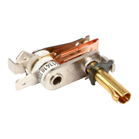
I
nsTallaTIOn
Thermostat Shaft
01608-REVA-122711
Thermostat Replacement Kits
Stock No. 55034
This kit replaces thermostat 81034
CONNECT LEAD FROM THE HEATING
8
ELEMENT TO THE STRAIGHT TERMINAL
ON THERMOSTAT.
Connect thermal cutout lead to angled
terminal on thermostat.
START THE THERMOSTAT SHAFT INTO
9
THE PANEL OPENING. Secure the wiring
with a wire tie.
PLACE THE ALUMINUM STANDOFF TUBE
J
OVER THE STUD not used to mount
the heating element and position the
thermostat bracket on the studs.
Install the lockwashers and start
•
the nuts onto the studs.
Do not tighten the nuts yet.
•
ROTATE THE HEATING ELEMENT as
K
needed to center the element terminals in
the rectangular opening in the thermostat
bracket.
Make sure that the dimple in the
thermostat bracket seats in the hole in
the heating element, then tighten the
bracket mounting nuts.
POSITION THE INSULATION BLOCK ON
L
THE THERMOSTAT BRACKET.
INSTALL THE BOTTOM WRAPPER and
M
secure it with four screws.
INSTALL KNOB by aligning knob groove
N
with spline on new thermostat shaft, then
push knob onto shaft (Tighten the knob
setscrew if used.)
PLUG UNIT INTO POWER SOURCE.
O
CALIBRATE UNIT per calibration
P
instructions on the following page.
Thermal Cutout Lead
connects to
Angled Terminal
Heating Element Lead
connects to
Straight Terminal
Advertisement

Related Manuals for Server 55034


Summary of Contents for Server 55034
- Page 1 This gives instructions for thermostat you. Turn the two black 1/4 turn fasteners replacement the 04400 DS DUAL SERVER at the bottom of the picture, 1/4 turn CONNECT LEAD FROM THE HEATING Series 81 to present.
- Page 2 WHEN THE TEMPERATURE REACHES THE Thermostat Replacement Kits • Hexagonal Wrench or Allen "COOL TO" TEMPERATURE, turn calibration Wrench (1.5 mm)-included in Stock No. 55034 screw counterclockwise until a soft audible Kit #55034 click is heard. This kit replaces thermostat 81034 •...
Need help?
Do you have a question about the 55034 and is the answer not in the manual?
Questions and answers