
Related Manuals for Guralp Systems 40T


Summary of Contents for Guralp Systems 40T
- Page 1 Güralp 40T Operator's Guide Document No: MAN-040-0001 Issue F, June 2019 Designed and manufactured by Güralp Systems Limited 3 Midas House, Calleva Park Aldermaston RG7 8EA England...
-
Page 2: Table Of Contents
3.4.1 Adjusting the mass position offsets manually............11 3.4.2 Adjusting the mass position offsets with an HCU..........12 3.4.3 Zeroing a 40TD digital instrument..............13 3.4.4 Digital nulling operation..................16 4 Installing the 40T......................17 4.1 Installation notes......................17 4.2 Installing in vaults......................18 4.2.1 Choosing a location....................18 4.2.2 Temperature stability..................19... - Page 3 Güralp 40T Preliminary Notes 4.3.1 Other installation methods.................22 5 Calibrating the 40T......................25 5.1 The calibration pack....................25 5.1.1 Poles and zeroes....................25 5.1.2 Frequency response curves................26 5.1.3 Obtaining copies of the calibration pack............27 5.2 Calibration methods....................28 5.3 Calibration with Scream!....................28 5.3.1 Sensor response codes..................32 5.4 Calibration with a hand-held control unit..............32...
-
Page 4: Preliminary Notes
Güralp 40T Preliminary Notes Preliminary Notes Proprietary Notice The information in this document is proprietary to Güralp Systems Limited and may be copied or distributed for educational and academic purposes but may not be used commercially without permission. Whilst every effort is made to ensure the accuracy, completeness and usefulness of the information in the document, neither Güralp Systems Limited nor any employee... -
Page 5: Introduction
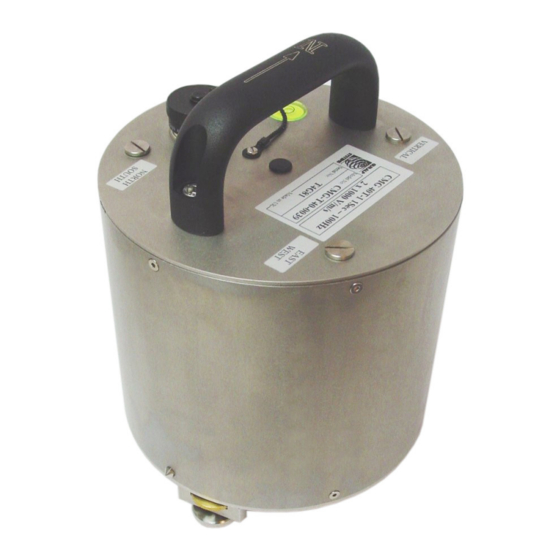
Güralp 40T Introduction Introduction The Güralp 40T is a lightweight seismometer consisting of three sensors in a sealed, stainless steel case, which can measure the north/south, east/west and vertical components of ground motion simultaneously. MAN-040-0001 Issue F - June 2019... -
Page 6: Response Options
Because of this, the 40T is ready to record ground movements as soon as you provide it with power. In addition, the sensor does not have to be levelled or centred as long as the base is within 3°... -
Page 7: First Encounters
First encounters Handling notes Although the 40T has a rugged design, it is still a sensitive instrument, and can be damaged if mishandled. If you are at all unsure about the handling or installation of the device, you should contact Güralp Systems for assistance. -
Page 8: The Hand-Held Control Unit
To monitor the low-gain outputs, switch the dial to V, N/S or E/W LOW VEL • according to the component you want to monitor. To monitor the high-gain outputs (on a 40T with that option), switch the dial • to V, N/S or E/W HIGH VEL. -
Page 9: Calibration
See Chapter 5 on page 25 for full details. 3.2.2.3 Control commands If you have ordered a 40T with the remote null facility, you can zero its mass position offsets from the HCU. 1. Select the component you want to centre from the CENTRING SELECT dial. -
Page 10: Levelling The Instrument
The velocity outputs of the 40T are set at the factory to a nominal value below ±3 mV. Once the instrument is installed and has reached thermal equilibrium with its environment, these outputs should be similar to the factory-set value. -
Page 11: Adjusting The Mass Position Offsets Manually
Güralp 40T First encounters The Güralp 40T can be ordered with a option for automated “digital nulling”. See section 3.4.4 on page 16 for more information and instructions for using this function. 3.4.1 Adjusting the mass position offsets manually The 40T has three potentiometers (“pots”) accessible within its casing, which should be used to remove any DC offsets electronically: 1. -
Page 12: Adjusting The Mass Position Offsets With An Hcu
6. Repeat steps 2 – 5 for the North/South and East/West components. 3.4.2 Adjusting the mass position offsets with an HCU Some 40T units are equipped with a remote mass centring option, which allows you to adjust the internal potentiometers by applying voltages across control lines to the sensor: 1. -
Page 13: Zeroing A 40Td Digital Instrument
3.4.3 Zeroing a 40TD digital instrument The offset potentiometers in a 40TD are in the same place as on the 40T. To access them, you will need to remove the digitiser module, which lies on top of the sensor itself. You can monitor the mass position outputs of the sensor using a Hand-held Control Unit and an adapter cable, available from Güralp Systems. - Page 14 Güralp 40T First encounters Warning: Güralp instruments are assembled at sea level. If working at altitude, there may be a considerable pressure differential. Take care that the vent cap does not “fly off” when released, causing injury. 3. Using a hexagonal wrench, remove the screws holding the digitiser module onto the sensor.
- Page 15 Güralp 40T First encounters 5. Carefully lift off the digitiser module, and unplug the ribbon cable from the sensor electronics. 6. Attach a Hand-held Control Unit and adapter cable to the ribbon connector, and power up the sensor through the control unit.
-
Page 16: Digital Nulling Operation
3.4.4 Digital nulling operation The Güralp 40T sensor can be ordered with an option for automated “Digital nulling”. This removes the need to manually adjust the internal potentiometers to achieve a near zero mass position output for each component. It comprises a micro-controller and three digital potentiometers that replace the standard electromechanical pots. -
Page 17: Installing The 40T
Güralp 40T Installing the 40T Installing the 40T Installation notes For the best possible results, a seismometer should be installed on a seismic pier in a specially-built vault, where conditions are near perfect. Here, wave-trains arriving at the instrument reflect very well the internal motion of subsurface rock formations. -
Page 18: Installing In Vaults
Installing the 40T Installing in vaults The 40T is a sensitive instrument designed to measure extremely small movements of the ground. These movements are the sum of all the vibrations arriving at the instrument: as well as distant earthquakes and nearby tremors, the ground responds to surf on nearby beaches, quarry blasts, heavy machinery, traffic, and even people moving around the building. -
Page 19: Temperature Stability
4.2.2 Temperature stability The 40T can operate over a wide temperature range (–10 °C to +75 °C). However, the sensor mass is sensitive to fluctuations in local temperature. This affects the response of the instrument at long periods. Sunlight and other bright lights can also cause small mechanical stresses that will be detected by the sensor. -
Page 20: Other Considerations
Güralp 40T Installing the 40T 4.2.3 Other considerations The sensor and cables should be situated well away from other electrical • cables and appliances. Stray radiation from these sources may interfere with the sensor's electronics. The sensor should be placed on a smooth, level surface free from cracks. - Page 21 Güralp 40T Installing the 40T Ideally, the sensor should rest directly on the bedrock for maximum coupling to surface movements. However, if bedrock cannot be reached, good results can be obtained by placing the sensor on a granite pier on a bed of dry sand.
-
Page 22: Other Installation Methods
Güralp 40T Installing the 40T 5. Alternatively, if time allows and granite is not available, prepare a concrete mix with sand and fine grit, and pour it into the hole. Agitate (“puddle”) it whilst still liquid, to allow it to flow out and form a level surface, then leave to set. - Page 23 Güralp 40T Installing the 40T Some installations introduce a layer of ceramic tiles between a rock or concrete plinth and the seismometer (left): However, noise tests show that this method of installation is significantly inferior to the same concrete plinth with the tiles removed (right). Horizontal sensors show shifting due to moisture trapped between the concrete and tiling, whilst the vertical sensors show pings as the tile settles.
- Page 24 Güralp 40T Installing the 40T MAN-040-0001 Issue F - June 2019...
-
Page 25: Calibrating The 40T
Velocity Output (Differential) : The sensitivity of each component to velocity at 1 Hz, in volts per m/s. Because the 40T uses balanced differential outputs, the signal strength as measured between the +ve and –ve lines will be twice the true sensitivity of the instrument. -
Page 26: Frequency Response Curves
5.1.2 Frequency response curves The frequency response of each component of the 40T is described in the normalised amplitude and phase plots provided. The response is measured at low and high frequencies in two separate experiments. Each plot marks the low-frequency and high-frequency cut-off values (also known as –3 dB or half-power points). -
Page 27: Obtaining Copies Of The Calibration Pack
Güralp 40T Calibrating the 40T If you want to repeat the calibration to obtain more precise values at a frequency of interest, or to check that a sensor is still functioning correctly, you can inject calibration signals into the system using a Güralp digitiser or your own signal generator, and record the instrument's response. -
Page 28: Calibration Methods
Calibration methods Velocity sensors such as the 40T are not sensitive to constant DC levels, either as a result of their design or because of an interposed high-pass filter. Instead, three common calibration techniques are used. - Page 29 Güralp 40T Calibrating the 40T 1. In Scream!'s main window, right-click on the digitiser's icon and select Control..Open the Calibration pane. 2. Select the calibration channel corresponding to the instrument, and choose Broadband Noise. Select the component you wish to calibrate, together with a suitable duration and amplitude, and click the button.
- Page 30 Güralp 40T Calibrating the 40T 4. If the returning signal is saturated, retry using a calibration signal with lower amplitude, until the entire curve is visible in the WaveView window. 5. If you need to scale one, but not another, of the traces, right-click on the trace and select Scale..
- Page 31 Güralp 40T Calibrating the 40T Most data can be found on the calibration sheet for your sensor. Under Instrument response , you should fill in the sensor response code for your sensor, according to the table below. Instrument Type should be set to the model number of the sensor.
-
Page 32: Sensor Response Codes
5.3.1 Sensor response codes Units Sensor Sensor type code (V/A) 40T-1 or 6T-1, 1 s – 50 Hz response CMG-40_1HZ_50HZ 40T-1 or 6T-1, 1 s – 100 Hz response CMG-40_1S_100HZ 40T-1 or 6T-1, 2 s – 100 Hz response CMG-40_2S_100HZ 40T-1 or 6T-1, 10 s –... - Page 33 40T. The calibration resistor is placed in series with the transducer. Depending on the calibration signal source, and the sensitivity of your recording equipment, you may need to increase by adding further resistors to the circuit.
-
Page 34: Connector Pin-Outs
Güralp 40T Connector pin-outs Connector pin-outs Output port and breakout box RECORDER connector This is a standard 26-pin military specification bayonet plug, conforming to MIL-DTL-26482 (formerly MIL-C-26482). A typical part-number is 02E-16-26P although the initial “02E” varies with manufacturer. Suitable mating connectors have part-numbers like ***-16-26S and are available from Amphenol, ITT Cannon and other manufacturers. - Page 35 Pressing ENABLE and CENTRE on a Güralp 3ESP hand- held control unit activates pin U and switches the 40T into one-second mode for as long as the buttons are held down. You must do this before you can monitor mass position outputs, e.g.
-
Page 36: Output Port And Breakout Box Recorder Connector (High-Gain Option)
Güralp 40T Connector pin-outs Output port and breakout box RECORDER connector (high-gain option) These units use the same plug with the following pin assignments. High gain velocity outputs are denoted HGV. This is a standard 26-pin military specification bayonet plug, conforming to MIL-DTL-26482 (formerly MIL-C-26482). -
Page 37: Breakout Box Power Connector
Güralp 40T Connector pin-outs Breakout box power connector This is a standard 10-pin “mil-spec” plug, conforming to MIL-DTL-26482 (formerly MIL-C-26482). A typical part-number is 02E-12-10P although the initial “02E” varies with manufacturer. Suitable mating connectors have part-numbers like ***-12-10S and are available from Amphenol, ITT Cannon and other manufacturers. -
Page 38: Specifications
Güralp 40T Specifications Specifications In the interests of continual improvement with respect to design, reliability, function or otherwise, all product specifications and data are subject to change without prior notice. SYSTEM Technology Force feedback velocity sensor Configuration / Topology Triaxial orthogonal (ZNE) - Page 39 Güralp 40T Specifications CALIBRATION Calibration input Independent signal and enable lines exposed on sensor connector CONNECTOR Single connector: Analogue 26-pin military-specification bayonet outputs, power input and connector. control inputs Post-hole option: 100 bar/10 MPa waterproof connector POWER Power supply voltage 10–36 V DC *...
-
Page 40: Revision History
Güralp 40T Revision history Revision history 27 June, 2019 Removed coil constant section. Updated specifications. Updated some graphics. 14 November, 2016 Added “Levelling” section. 29 June 2016 Added safety warning about pressure-relief screw. Enhanced specifications. Minor edits elsewhere. 3 May 2016...
Need help?
Do you have a question about the 40T and is the answer not in the manual?
Questions and answers