Table of Contents
Advertisement
Quick Links
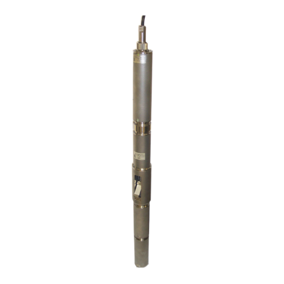
CMG-3TB
Operator's guide
Part MAN-BHO-0001
Designed and manufactured by
Güralp Systems Limited
3 Midas House, Calleva Park
Aldermaston RG7 8EA
England
Proprietary Notice: The information in this manual is
proprietary to Güralp Systems Limited and may not be
copied or distributed outside the approved recipient's
organisation without the approval of Güralp Systems
Limited. Güralp Systems Limited shall not be liable for
technical or editorial errors or omissions made herein,
nor for incidental or consequential damages resulting
from the furnishing, performance, or usage of this
material.
Issue C
2006-11-15
Advertisement
Table of Contents

Related Manuals for Guralp Systems CMG-3TB


Summary of Contents for Guralp Systems CMG-3TB
- Page 1 CMG-3TB Operator’s guide Part MAN-BHO-0001 Designed and manufactured by Güralp Systems Limited 3 Midas House, Calleva Park Aldermaston RG7 8EA England Proprietary Notice: The information in this manual is proprietary to Güralp Systems Limited and may not be copied or distributed outside the approved recipient's organisation without the approval of Güralp Systems...
-
Page 2: Table Of Contents
CMG-3TB Table of Contents 1 Introduction....................... 4 1.1 System configuration..................5 1.2 Digital borehole installations................6 1.3 The hole lock system..................7 The single-jaw hole lock..................7 The three-jaw hole lock..................9 2 Assembling the instrument..................11 2.1 Unpacking and packing..................11 2.2 Handling notes.................... - Page 3 Operator's guide Installing the Scream! extension............... 47 Installing the reference instrument..............47 Measuring the orientation.................. 48 Applying automatic rotation................53 4 Calibrating the 3TB....................55 4.1 The calibration pack..................55 Poles and zeroes....................56 Frequency response curves................57 Obtaining copies of the calibration pack............57 4.2 Calibration methods..................
-
Page 4: Introduction
CMG-3TB 1 Introduction The CMG-3TB is a three-axis seismometer consisting of three sensors stacked vertically in a sealed borehole sonde, designed for use in cased boreholes with diameters between 5” / 89 mm and 9” / 229 mm. The seismometer system is self-contained except for its 12 – 30 V power supply, which is provided through the same cable as the analogue data. -
Page 5: System Configuration
For example, a borehole or pit installation of a CMG-3TB or 3ESPB instrument with single-jaw hole lock has the following layout: CMG 3-series instruments are also suitable for installing in boreholes with sand backfill. -
Page 6: Digital Borehole Installations
CMG-3TB The CMG-3V sensor is identical to the vertical-component module of the 3TB instrument, allowing you to build mixed arrays of 3V and 3TB sensors with identical response characteristics. 1.2 Digital borehole installations The Güralp DM24 digitizer is available in a borehole sonde form. -
Page 7: The Hole Lock System
Operator's guide A digital borehole installation can be provided with RS232, RS422 or fibre-optic links to the surface, depending on the depth of the borehole. When a downhole digitizer is present, it takes the place of the strain relief unit in the borehole. The surface unit also takes a slightly different form, with a serial connector allowing you to attach a modem or other communications link. - Page 8 CMG-3TB borehole, providing two line contacts; only the tips of the skids come into contact with the borehole, • providing three point contacts; a single skid is combined with a pad to provide one line and one • point contact; or three studs provide three point contacts.
-
Page 9: The Three-Jaw Hole Lock
Operator's guide Studs have the advantage of being smaller than skids, but the contact points are very close to each other. You should evaluate the various locking methods available to see which works best in your borehole. The spring inside the lock provides around 60 kg of force at its locking position. - Page 10 CMG-3TB held parallel to the axis of the borehole and prevented from twisting or slipping under the influence of ground vibrations. Issue C...
-
Page 11: Assembling The Instrument
Operator's guide 2 Assembling the instrument 2.1 Unpacking and packing The 3TB seismometer is delivered in a single transportation case, with the sensor system and hole lock mechanism (if ordered) packed separately. The packaging is specifically designed for the 3TB and should be reused whenever you need to transport the sensor. -
Page 12: Assembling The 3Tb
CMG-3TB installation of the device, you should contact Güralp Systems for assistance. Do not bump or jolt any part of the sensor when handling or • unpacking. Keep the sonde sections vertical wherever possible. Carry them • by hand and store in a safe rack. Never drag or roll the sonde. - Page 13 Operator's guide 1. Ensure that the “O”-ring seals on the hole lock and sensor sections are clean and well greased. 2. Stand the horizontal sensor on the ground with the packing cap at the top, and support it to prevent it from falling over. This can be done either by using an assistant to hold the casing steady, or by strapping it to a support such as a bench leg.
- Page 14 CMG-3TB connectors. Ensure that each is connected to its correct counterpart. hole lock unit at an angle above the horizontal sensor and join the connectors. Ensure that each is connected to its correct counterpart. The wires are fairly short, so you will need a second person to hold the instrument whilst you connect them.
- Page 15 Operator's guide 6. Push the hole lock unit into the horizontal sensor housing, twisting to align the holes. 7. Fit twelve M3×8 cap screws into the holes in the joint flange. 8. When all twelve screws are fitted, begin to tighten them with a ball-ended Allen screwdriver.
-
Page 16: Disassembling The Instrument
CMG-3TB 11.Push the vertical sensor housing into the hole lock–actuator section, twisting to align the holes. 12.Fit twelve M3×8 screws into the holes and tighten. 13.If you are using a single-jaw hole lock unit, attach skids or studs to the sonde as appropriate for your installation, using the fastenings provided. -
Page 17: Control Units
Operator's guide scratching the other components. 2.5 Control units The 3TB is operated from the surface through various control units. All the 3TB's functions can be accessed through one or other unit. Most can be removed from the site once the instrument is ready for use. Some of these control units are optional and may not have been supplied with your installation. -
Page 18: Calibration
CMG-3TB digitizer. In systems using downhole digitizers, this is replaced by a 10-way mil-spec serial connector for attaching to a Data Communications Module (DCM), modem other communications link. The CONTROL connector is a 26-way mil-spec plug intended • for connecting to an external controller or Handheld Control Unit, with the same pin out as the RECORDER connector. -
Page 19: Centring
Operator's guide need to move the instrument. To unlock the instrument, hold down the ENABLE and UNLOCK buttons (or the UNLOCK switch on a breakout box) for at least six seconds. The sensor's microcontroller will free the vertical, N/S and E/W sensor masses in turn and ready them for use. -
Page 20: Connections
CMG-3TB Connections The HCU provides two identical 26-pin connectors for attaching to the HCU or • RECORDER connectors of the breakout box, and a 10-pin connector through which you can power the • instrument, if desired. The power pins on this connector are directly connected to those on the SENSOR POWER connector of the breakout box. -
Page 21: Calibration And Control
Operator's guide You can set the range of the meter with the RANGE switch. • When switched to 10 V, the meter ranges from –10 to +10 V (as marked.) When switched to 1 V, the range is –1 to +1 V. Calibration and control You can calibrate a 3TB sensor through the HCU by connecting a signal generator across the yellow and green CALIBRATION SIGNAL... -
Page 22: Operating The Hole Lock
CMG-3TB To measure the attitude of a 3TB instrument: 1. Connect the inclinometer monitor unit to the CONTROL connector of the breakout box. 2. Switch the ON/OFF switch on the monitor unit to the ON position. The inclinometer is powered separately from other parts of the system;... -
Page 23: Engaging The Hole Lock
Operator's guide Caution: The hole lock may be using high-voltage mains (outlet) power. 1. Connect the hole lock control unit to the HOLELOCK POWER connector of the breakout box, and to a mains power supply. Alternatively , connect a 12 – 24 V DC power supply across the input terminals of the hole lock control unit. -
Page 24: Disengaging The Hole Lock
CMG-3TB unit, there will be an additional dial compared to the unit pictured; turn this until the built-in ammeter reads around 0.1 2. When the arm makes contact with the borehole casing, the current will drop slightly. Continue holding the switch in the EXTEND JAW position. - Page 25 Operator's guide 0 V. To retract the jaw, reverse the polarity so that the Hole Lock • Motor Return pin is at +12 V and the Hole Lock Motor pin is at 0 V. November 2006...
-
Page 26: Installing The 3Tb In A Borehole
CMG-3TB 3 Installing the 3TB in a borehole Before installing any instrument in a borehole, you should prepare the installation site. Clean the area around the borehole head, so there is clear access • all around it. Keep the borehole capped at all times except when inserting or •... - Page 27 Operator's guide 2. If applicable, you should test the hole lock mechanism before installing the sensor. For safety reasons, the hole lock is normally supplied with the arm extended. To test the mechanism, connect the signal cable to a breakout box and Holelock Control Unit, and attempt to retract the hole lock arm (see Section 2.6, page 22.) If this fails, you should contact Güralp Systems.
- Page 28 CMG-3TB 4. Attach the lifting loop to the sensor using four M5×16 screws (provided). 5. Join the loop to the bottom of the strain relief mechanism using the linking cable provided. 6. Using a small winch, hoist up the sensor package and strain relief mechanism until both are hanging by the lifting cable, with the strain relief mechanism extended.
- Page 29 Operator's guide 7. Fix the signal cable to the main lifting cable about 1 m above the strain relief mechanism using a metal clamp (a nylon cable tie may be sufficient for shallow installations.) Leave a little slack in the signal cable between the clamp and the strain relief mechanism.
- Page 30 CMG-3TB fails to register ground movements, contact Güralp Systems. 15.Lock the sensor masses once more, tension the load bearing cable and retract the hole lock arm. 16.Gently lower the sensor to the required depth. At approximately 20 m intervals, fix the signal cable to the load bearing cable using metal clamps (nylon cable ties every 5 m may be sufficient for shallow installations).
-
Page 31: Installing A Sensor Using Sand Backfill
Operator's guide 3.2 Installing a sensor using sand backfill Dry sand backfill is a convenient and effective way of installing a borehole or posthole sensor in a time-stable environment. The presence of sand not only fixes the sensor in place at the bottom of the hole, but also reduces noise due to air convection. -
Page 32: Procedure
CMG-3TB Procedure To install a sensor at the bottom of a borehole of known depth using sand backfilling: 1. Measure or calculate the physical volume of the unit which is to be installed in the borehole. (The volume of a cylinder v = πr... - Page 33 Operator's guide 5. Attach the lifting loop to the sensor using four M5×16 screws (provided). 6. Join the loop to the bottom of the strain relief mechanism using the linking cable provided. 7. Hoist up the sensor package and strain relief mechanism until both are hanging by the lifting cable, with the strain relief mechanism extended.
- Page 34 CMG-3TB 8. Fix the signal cable to the main lifting cable about 1 m above the strain relief mechanism using a metal clamp (a nylon cable tie may be sufficient for shallow installations.) Leave a little slack in the signal cable between the clamp and the strain relief mechanism.
- Page 35 Operator's guide 14.Whilst monitoring the depth of the sensor, carefully approach the sand layer at the bottom of the borehole. The lifting cable will go slack when the sensor makes contact with the sand. If the lifting cable goes slack before the sensor has reached the sand layer, it may have become caught on a bad joint or lip in the borehole;...
-
Page 36: Assembling The Winch
CMG-3TB 3.3 Assembling the winch If required, Güralp Systems can provide a winch suitable for installing a borehole sensor. The winch and tripod are supplied as a set of parts which you can assemble on site: There are two sections for each leg of the tripod. The upper sections are pre-attached to the head of the tripod;... - Page 37 Operator's guide 3. Erect the tripod above the borehole, and run the yellow retaining tape through the loops. Fasten together the ends of the tape. 4. The lifting cable is supplied with a loop at one end. Run this over one of the pulleys at the top of the tripod, so that the loop hangs down between the legs.
- Page 38 CMG-3TB finishing at the leg with the winch attached. 7. Take the end of the load-bearing cable without the loop, and screw it to the axle inside the winch using a 4 mm Allen key (provided) as shown. 8. Attach the handle to the side of the winch opposite the ratchet mechanism, and fasten it in place with a collar, washer and screw, using the larger Allen key.
- Page 39 Operator's guide 9. Wind the cable onto the winch by rotating the handle. Ensure that the cable builds up neatly across the drum. Continue winding until the loop on the other end is as high as you need it to install the equipment. If the ratchet prevents you from winding the cable on, twist the metal boss in the DOWN direction to free the cable.
-
Page 40: Earthing A Borehole Sensor
CMG-3TB 11.Hang the strain relief unit and instrument(s) from the loop at the other end of the cable. You are now ready to lower the assembly into the borehole as described above. 3.4 Earthing a borehole sensor To achieve the best performance from any borehole instrument, you... - Page 41 Operator's guide which is connected to a local ground plate. All earth lines for equipment in the installation, such as the casings of the transformers and of the sensor electronics, as well as the signal ground line from the sensor, should be connected to this plate. The best local earth point in many installations is the borehole itself.
- Page 42 CMG-3TB An earth strap can be used to ensure a good connection. If the lower borehole is filled with salt water, the instrument will be adequately grounded without any further action. Fresh water is an inferior conductor. In a dry or sand-filled borehole, or one with a non-conducting casing, you will need to ensure the sonde is grounded by some other means.
- Page 43 Operator's guide The best option is often to attach the sensor housing to an earth line brought out to the surface and attached to a metal stake driven into the ground nearby. The sensor's load bearing cable is suitable for this purpose, provided it is secured to the sensor's lifting loop with a metallic clamp as shown below.
-
Page 44: Installations With Dc Power Supplies
CMG-3TB For boreholes with a metallic casing at the bottom and plastic above, we recommend connecting a cable between the sensor housing and the ground plate so that the lower borehole casing acts as the earthing point. Again, the If there is a significant distance (>30 m) between the borehole and the surface installation, the resistance of the earth cable may make it impractical to use the borehole as an earthing point. -
Page 45: External Lightning Protection
Operator's guide As with AC installations, if the borehole is more than around 30 m from the surface enclosure, you will need to provide a second earthing point for the local ground plate. DC power is most commonly available at self-contained installations with power supplied from batteries, solar panels, or a wind generator. -
Page 46: Levelling And Centring
CMG-3TB 3.5 Levelling and centring Once it is installed, you should level and centre the instrument ready for use. This can be done using the various surface control units: 1. Connect an inclinometer monitor unit to the breakout box. 2. Turn on the borehole control unit using the ON/OFF switch under the transparent flap. -
Page 47: Downhole Orientation
Operator's guide 3.6 Downhole orientation Once the sensor is installed inside the borehole, you will need to measure its orientation with respect to the compass points. There is no need to rotate the sensor itself, since the data can be rotated algorithmically after it is digitised. -
Page 48: Measuring The Orientation
CMG-3TB each one to settle. This process takes at least 12 hours. Measuring the orientation 1. Run Scream!. Open the File – Setup window, and select the Display tab. 2. Under Stream Buffering , increase the buffer size to an amount which will hold all your experimental data. - Page 49 Operator's guide The N and E streams are the “North/South” and “East/West” components of the downhole instrument. The X stream is the North/South component of the reference instrument. If you are using a separate digitizer, the reference instrument will appear on the North/South component of the other digitizer, instead of the X stream.
- Page 50 CMG-3TB When you are happy with the selection, release the mouse button, but keep SHIFT held down. 11.When the menu appears, release the SHIFT key. Select Relative Orientation from the menu that appears. Two small windows will appear: a small progress window, and...
- Page 51 Operator's guide The two-stage algorithm rotates the N/S and E/W components of the sensor being tested in small steps. It measures first the amplitude similarity, and then the coherence between this new N/S component and the reference N/S component, for a number of rotation angles. The error in the final calculation is around 2.5 °.
- Page 52 CMG-3TB the signal, i.e. the time series that a sensor in perfect N/S orientation would have produced: 14.You can perform more accurate calculations by narrowing the search range. This is done in the two entry boxes on the Coherence vs Angle window: the first denotes the centre of the new search, and the second its range.
-
Page 53: Applying Automatic Rotation
Operator's guide Our sample instrument is thus aligned at –90.35 ± 0.07 °. 16.The error given is only a rough estimate. You should repeat the orientation experiment several times using different data sets. The true error in the computed orientation can be determined by observing the spread of the results. - Page 54 CMG-3TB You should see an ok prompt, indicating that the digitizer is ready to receive commands. 2. Type 0 rotation AZIMUTH where rotation is the angle of deviation from true North that you measured earlier, as a whole number of tenths of a degree.
-
Page 55: Calibrating The 3Tb
Operator's guide 4 Calibrating the 3TB 4.1 The calibration pack All Güralp sensors are fully calibrated before they leave the factory. Both absolute and relative calibration calculations are carried out. The results are given in the calibration pack supplied with each instrument: Works Order : The Güralp factory order number including the instrument, used internally to file details of the sensor's manufacture. -
Page 56: Poles And Zeroes
CMG-3TB Poles and zeroes Most users of seismometers find it convenient to consider the sensor as a “black box”, which produces an output signal V from a measured input x. So long as the relationship between V and x is known, the details of the internal mechanics and electronics can be disregarded. -
Page 57: Frequency Response Curves
Operator's guide Frequency response curves The frequency response of each component of the 3TB is described in the normalised amplitude and phase plots provided. The response is measured at low and high frequencies in two separate experiments. Each plot marks the low-frequency and high-frequency cutoff values (also known as –3 dB or half-power points). -
Page 58: Calibration Methods
CMG-3TB 4.2 Calibration methods Velocity sensors such as the 3TB are not sensitive to constant DC levels, either as a result of their design or because of an interposed high-pass filter. Instead, three common calibration techniques are used. Injecting a step current allows the system response to be •... - Page 59 Operator's guide Depending on the digitizer type, sine-wave, step and broadband noise signal generators may be available. In this section, broadband noise calibration will be used to determine the complete sensor response in one action. Please refer to the digitizer's manual for information on other calibration methods.
- Page 60 CMG-3TB sensors' own measurements. If you cannot see the calibration signal, zoom into the Waveview using the scaling icons at the top left of the window or the cursor keys. Drag the calibration stream Cn across the Waveview window, so that it is at the top.
- Page 61 Operator's guide Most data can be found on the calibration sheet for your sensor. Under Instrument response , you should fill in the sensor response code for your sensor, according to the table below. Instrument Type should be set to the model number of the sensor.
-
Page 62: Sensor Response Codes
Sensor response codes Units Sensor Sensor type code (V/A) CMG-3TB, 30 s – 50 Hz response CMG-3B_30S_50HZ CMG-3TB, 100 s – 50 Hz response CMG-3B_100S_50HZ CMG-3TB, 120 s – 50 Hz response CMG-3B_120S_50HZ CMG-3TB, 360 s –... -
Page 63: The Coil Constant
Operator's guide Depending on the calibration signal source, and the sensitivity of your recording equipment, you may need to increase R by adding further resistors to the circuit. 4.5 The coil constant The feedback coil constant K is measured at the time of manufacture, and printed on the calibration sheet. -
Page 64: Inside The 3Tb
0.5 s, whilst the horizontal sensor has an unstressed flat spring with a natural period around 1 s. CMG-3TB sensors have no spurious resonances below 140 Hz, and weigh around 180 g. The small boom size and stiff springs allow three independent instruments to be mounted within the casing, together with all the associated feedback electronics. - Page 65 Operator's guide The signal voltages output by the 3TB are proportional to ground velocity, and are transmitted from the instrument on balanced differential lines. In addition, mass position signals are sent as single- ended circuits referred to analogue ground on the output plug. The 3TB also receives control signals, which are used to clamp and unclamp the masses, and to run the motors which level and centre the instrument once in position.
-
Page 66: The Control System
CMG-3TB 5.2 The control system The internal operations of the 3TB are supervised by a control microprocessor, which drives the mass clamping and centring adjustment motors. It responds to commands sent on three input lines by grounding for 0.2 – 7 seconds. -
Page 67: Unlock
Operator's guide In the five-stage process, each mass in turn is locked with a motorised micrometer (stages 1, 2, 4), and the N/S and E/W sensor bases are tilted to their end stops (stages 3 and 5). At some point during each tilting stage, the position of the relevant mass will flip to one or other side. - Page 68 CMG-3TB Again, you can use the BUSY LED to monitor the progress of unlocking. 1. The instrument checks to see whether the vertical mass is locked, and unlocks it if necessary. 2. The vertical mass is centred by applying pulses to the motor.
-
Page 69: Centre
Operator's guide CENTRE This command re-centres the masses. If the masses are clamped, or if the sensor mass positions do not exceed ± 1.2 V, the CENTRE command does nothing. Otherwise, it attempts to zero the output of the vertical, N/S and E/W sensors in sequence by exerting small extra forces on the boom. -
Page 70: The Feedback System
CMG-3TB After the sensor unlocks the masses, the first round of centring has to move the N/S and E/W components all the way from their end stops, whilst the Z component is often closer to the proper position. Because of this, the first Z centring operation takes much less time than the others, and you may not notice it. -
Page 71: Hybrid Feedback
Operator's guide In a feedback seismometer with a displacement transducer, it is essential to monitor the acceleration output. This provides the position of the displacement transducer and therefore also the mass position, as the displacement transducer is attached to the sensor inertial mass. The sensor should always be operated with the displacement transducer centred or nulled, so that the response to input acceleration is linear. -
Page 72: Conventional-Response Feedback
CMG-3TB Conventional-response feedback The conventional-response feedback system has an additional parallel feedback circuit, consisting of a non-inverting integrator in series with a resistor. This arrangement results in two poles at specified frequencies. The velocity response of a conventional-response system is defined by a transfer function identical to that of a conventional long-period sensor with a damping constant of 0.707 (1/√2) - Page 73 Operator's guide November 2006...
-
Page 74: Connector Pinouts
CMG-3TB 6 Connector pinouts This table combines the pinouts for all connectors on the borehole sensor and breakout box. Control signals are normally active low, but active high versions can be supplied on request. Column (a): The single connector on a 3TB sensor, a 32-way mil-spec waterproof plug (02E-19-32P). - Page 75 Operator's guide Centre Direct Unlock Lock Acc/Vel mode switch* Signal ground Control signal ground Case ground *The Acc/Vel mode switch pin is used by the automatic centring process to switch the instrument temporarily into a mode where its response at normal frequencies is flat to acceleration, and thus in linear proportion to the mass position.
-
Page 76: Specifications
CMG-3TB 7 Specifications Hybrid sensors Velocity output bandwidth 0.1 – 50 Hz High pass filter output flat 0.01 Hz – spec * to acceleration High pass filter output flat spec – 50 Hz* to velocity Mass position output DC – 0.1 Hz... - Page 77 Operator's guide *spec refers to the quoted frequency response value, e.g. , for a “30 s” sensor, the value of spec would be 30 s = 0.033 Hz. **Sensors are available with a range of sensitivities between 2 × 750 and 2 ×...
-
Page 78: Revision History
CMG-3TB 8 Revision history 2006-11-15 C Updated Scream! and SOH; added revision history 2005-05-12 B Original document Issue C...
Need help?
Do you have a question about the CMG-3TB and is the answer not in the manual?
Questions and answers