Advertisement
Quick Links
Installation, Operation and Maintenance Instructions
Please read all instructions before attempting installation or operation of these units
SAVE THESE INSTRUCTIONS FOR FUTURE USE
P
N
.
UBLICATION
O
855355259
revD
ADJUST-A-GOAL
Models: 1131 and 1171
Revised Feb. 01, 2020
Advertisement

Subscribe to Our Youtube Channel
Related Manuals for Gared PSS ADJUST-A-GOAL

Summary of Contents for Gared PSS ADJUST-A-GOAL
- Page 1 ADJUST-A-GOAL Models: 1131 and 1171 Installation, Operation and Maintenance Instructions Please read all instructions before attempting installation or operation of these units SAVE THESE INSTRUCTIONS FOR FUTURE USE UBLICATION 855355259 revD Revised Feb. 01, 2020...
- Page 2 Table of Contents Section Page No. Introduction Cautions and Warnings Assembly and Setup 3-13 Electrical Installation Operation Maintenance Accessories Introduction Thank you for your purchase of a basketball goal height adjuster. To ensure that our equipment will provide years of use to you, we are including this installation, operation, and maintenance guide.
- Page 3 HEIGHT ADJUSTER Read and understand the following warnings to prevent possible personal injury and potential damage to the equipment during assembly, setup, and operation. Before proceeding with assembly, read all instructions and assembly procedures. Make sure all parts have been received and are not damaged.
- Page 4 HEIGHT ADJUSTER INSTALLATION INSTRUCTIONS Tools Required: 7/16 wrench and socket 1/2 wrench and socket 9/16 wrench and socket Rubber Mallet 3/4 wrench and socket 15/16 wrench and socket 11/16 wrench and socket Ratchet corresponding to sockets ½” Torque wrench (150 ftlbs +) 3/8”...
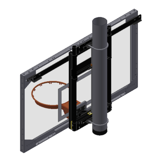
- Page 5 HEIGHT ADJUSTER 1.) The picture on the front of this manual is not typical of all installed units. Remove the height adjuster from the packaging. The basic 1131 unit is shown below. If model 1171 or 1171-220 have been purchased, install the electric height adjuster on the mast and install board and goal the same as the 1131 manual height adjuster.
- Page 6 HEIGHT ADJUSTER 2.) Attach the Direct Mount Extension (DME) to the front of the height adjuster frame with the bolts supplied. Tighten the bolts securely. See below. PN: 4404 KIT, 63” X 36” RECT BOARD MOUNT PN: 4405 KIT, 35” X 20” FAN BOARD MOUNT 3.) The DME is your starting point for any board you install on this equipment.
- Page 7 HEIGHT ADJUSTER 4.) Attachment of the upper section of the narrow or wide boards is dependent upon how the backboard support angle and adjustable feet are attached. First attach the adjustable feet to the rear of the board as shown in the following illustrations. The part number for the adjustable foot is 503852349.
- Page 8 HEIGHT ADJUSTER 5.) Next attach to the correct backboard support angle for either the narrow or wide mounting application depending on which board you are attaching. The narrow board support angle, part number 504151667, has a 35” wide mounting configuration and is shown below. The wide board support angle, part number 504151666, has a 63”...
- Page 9 HEIGHT ADJUSTER 6.) There are several ways to mount the boards to the height adjuster using the backboard angles and the adjustable feet. See figures 1, 2, 3 and 4. Reference board numbers under each illustration. FIGURE 1: use for: 1301B, 1270B, 1260B, 1272B, 1401B, 1370B, AFRG48 FIGURE 2: use for: 1750B, 1442B, AFRG42, LXP4200...
- Page 10 HEIGHT ADJUSTER FIGURE 3: use for: 1354B FIGURE 4: use for: 1342B The above figures are a quick reference of the orientation of the backboard support angles and the adjustable foot angle. In some cases the mounting of the backboard support angle will be on the top mounting tab of the height adjuster and in other cases it will use the bottom mounting tabs.
- Page 11 HEIGHT ADJUSTER 7.) Leave all hardware loose until all connections are made for the angles, board and DME. Install the height adjuster to the unit structure. Make sure the post is plum on all ceiling hung units before installation of the height adjuster. Refer to the instructions supplied with the ceiling hung backstop for plumbing the mast.
- Page 12 HEIGHT ADJUSTER HEIGHT ADJUSTER TO SINGLE POST INSTALLATION PN: 1408 KIT, AAG TO 6 5/8” MAST 1. After board and goal have been adjusted for plumb, level, and the proper height A.F.F., make sure all 5/8" Mast Clamp U-bolts have been torqued to 94 to 130 ft-lbs. 2.
- Page 13 HEIGHT ADJUSTER HEIGHT ADJUSTER TO WALL MOUNT INSTALLATION The following illustration shows how the height adjuster attaches to the wall mount frames. Use the 1/2” nuts and bolts provided to attach the frame two places top and bottom as shown. PN: 5741 KIT, AAG TO 63”...
- Page 14 HEIGHT ADJUSTER AAG TO DUAL POST INSTALLATION The following illustration shows how the height adjuster mounts to the dual post configuration. Use the small U-bolts two places top and bottom to bolt the height adjuster unit to the horizontal cross pipes as indicated. PN: 3510 Kit, AAG to 35”...
- Page 15 HEIGHT ADJUSTER Electrical Installation (1171 models) Electrical wiring should be completed by a qualified electrician. MINIMUM CIRCUIT REQUIREMENTS -DEDICATED 115VAC, 1PH, 60HZ, Wiring Schematic 115v 1ph 60hz 15 AMP SERVICE MOTOR SPECIFICATION -1/8HP 115VAC, 1PH, 60HZ,1.3 FLA -INSTANT REVERSING -AUTO RESET THERMAL O/L MINIMUM WIRE SIZE (copper wire, 3% max voltage drop) 0-430 ft....14 ga.
- Page 16 HEIGHT ADJUSTER OPERATION 1131 Manual Height Adjuster 1. Hook the Crank, option 9120-11-08, into Slide Lock casting on bottom of height adjuster. Pull down to unlock and turn crank counter clockwise to lift, clockwise to lower. Stop at any height between 10’ and 8’ goal height and remove crank. Do not crank forcibly past the stops.
- Page 17 HEIGHT ADJUSTER MAINTENANCE The following illustration shows the assembly of the manual height adjuster. The maintenance is the same for the electric version as well as the manual. The main slide tubes must be lubricated at all times. For typical installations, it should be lubricated every 6-8 months.
- Page 18 HEIGHT ADJUSTER Gared Holdings, LLC Performance Sports Systems Gared Sports 9200 E. 146 Street 9200 E. 146 Street Noblesville, IN 46060 Noblesville, IN 46060 800-848-8034 800-325-2682 www.perfsports.com www.garedsports.com...
Need help?
Do you have a question about the PSS ADJUST-A-GOAL and is the answer not in the manual?
Questions and answers
Adjust-A-Goal Model 1131 can a additional parts be ordered? (Part # 504151666) 63" wide mounting bracket. Need two (2). Or can i get the detention for the piece to make.