Table of Contents
Advertisement
Quick Links
Advertisement
Table of Contents

Subscribe to Our Youtube Channel
Related Manuals for Kentatsu KFHD12H0EN1


Summary of Contents for Kentatsu KFHD12H0EN1
- Page 1 DK15-01.01.29 TECHNICAL SERVICE MANUAL Fancoil unit Ceiling & Floor type Models: KFHD12H0EN1 KFHE12H0EN1 KFHD20H0EN1 KFHE20H0EN1 KFHD25H0EN1 KFHE25H0EN1 KFHD30H0EN1 KFHE30H0EN1 KFHD38H0EN1 KFHE38H0EN1 KFHD48H0EN1 KFHE48H0EN1 KFHD57H0EN1 KFHE57H0EN1 KFHD65H0EN1 KFHE65H0EN1 KFHD78H0EN1 KFHE78H0EN1...
-
Page 2: Table Of Contents
Ceiling & Floor Fan Coil Units Features ......................3 External Appearance ..................3 Products Lineup ..................... 4 Specifications ....................5 Dimensions ..................... 7 Service Spaces ....................9 Wiring Diagrams ................... 10 ... -
Page 3: Features
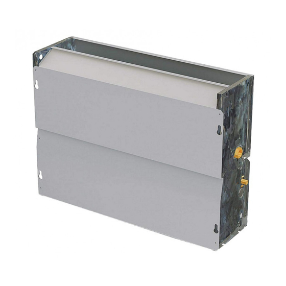
KFHD&KFHE Ceiling & Floor type 1. Features Flexible for installation, designed for horizontal/vertical, concealed/cabinet application Ceiling Installation Floor Installation Concealed Installation Air return form side or below for flexible choice Movable louver makes wide angle air flow 2. External Appearance Cased Type (KFHD) Uncased Type (KFHE) General Information... -
Page 4: Products Lineup
KFHD&KFHE Ceiling & Floor type 3. Products Lineup Model Air volume (CFM) Power supply KFHE / KFHD12H0EN1 KFHE / KFHD20H0EN1 KFHE / KFHD25H0EN1 KFHE / KFHD30H0EN1 KFHE / KFHD38H0EN1 220~240V-1Ph-50Hz KFHE / KFHD48H0EN1 KFHE / KFHD57H0EN1 KFHE / KFHD65H0EN1 KFHE / KFHD78H0EN1... -
Page 5: Specifications
KFHD&KFHE Ceiling & Floor type 4. Specifications KFHD_H0EN1 KFHE_H0EN1 Power supply V/Ph/Hz 220-240/1/50 255/215/190 425/360/320 510/430/380 680/580/510 Air flow (H/M/L) 150/125/110 250/210/190 300/250/220 400/340/300 Capacity (H/M/L) 1.15/0.93/0.89 1.87/1.74/1.59 2.53/2.25/1.88 3.27/2.84/2.54 Cooling Water flow rate Water pressure drop 18.3 10.1 14.2 26.3 Capacity (H/M/L) 1.52/1.29/1.14... - Page 6 KFHD&KFHE Ceiling & Floor type Specifications KFHD_H0EN1 KFHE_H0EN1 Power supply V/Ph/Hz 220-240/1/50 765/650/570 850/720/640 1020/870/765 1360/1160/1020 1530/1300/1150 Air flow (H/M/L) 450/380/335 500/420/375 600/510/450 800/680/600 900/760/675 Capacity (H/M/L) 3.97/3.58/3.15 4.85/4.41/3.72 5.64/5.02/4.46 6.52/5.75/4.36 7.85/7.19/6.55 Water flow rate 1121 1350 Cooling Water 23.1 11.4 24.3 pressure drop...
-
Page 7: Dimensions
KFHD&KFHE Ceiling & Floor type 5. Dimensions Cased type Dimensions (unit: mm) Size 1000 1000 1200 1200 1500 1500 1500 1284 1284 1284 1200 1200 1200 1226 1226 1226 General Information... - Page 8 KFHD&KFHE Ceiling & Floor type Uncased type Dimensions (unit: mm) Size 1250 1250 1250 1226 1226 1226 1200 1200 1200 1232 1232 1232 General Information...
-
Page 9: Service Spaces
KFHD&KFHE Ceiling & Floor type 6. Service Spaces Cased type ≥a ≥b ≥a a (mm) ≥a ≥a b (mm) Uncased type ≥a ≥b ≥a ≥b a (mm) ≥a ≥a b (mm) General Information... -
Page 10: Wiring Diagrams
KFHD&KFHE Ceiling & Floor type 7. Wiring Diagrams General Information... -
Page 11: Capacity Tables
KFHD&KFHE Ceiling & Floor type 8. Capacity Tables 9.1 Cooling capacity table EWT: Enter Water Temp. (℃); Δt: Temperature Difference (℃); DB: Dry Bulb Temp. (℃); WB: Wet Bulb Temp. (℃); TC: Total Cooling Capacity (kW); SC: Sensible Cooling Capacity (kW); WF: Water Flow (m3/h); WPD: Water Pressure Drop (kPa) Air inlet condition ∆t DB:26.7 WB:19.4... - Page 12 KFHD&KFHE Ceiling & Floor type Cooling capacity table Air inlet condition ∆t DB:26.7 WB:19.4 DB:27 WB:18 DB:27 WB:19 DB:27 WB:20 DB:29 WB:21 WF WPD WF WPD WF WPD WF WPD WF WPD 2.38 1.44 0.68 45.6 2.19 1.58 0.63 38.3 2.33 0.67 43.7 2.47 1.43 0.71 48.9 2.61 1.37 0.75 54.5 2.29 1.39 0.49 23.7 1.53 0.45 20.0 2.25 1.45 0.48 22.9 2.39 1.39 0.51 25.7...
- Page 13 KFHD&KFHE Ceiling & Floor type Cooling capacity table Air inlet condition ∆t DB:26.7 WB:19.4 DB:27 WB:18 DB:27 WB:19 DB:27 WB:20 DB:29 WB:21 WF WPD WF WPD WF WPD WF WPD WF WPD 3.22 1.94 0.92 64.0 2.96 2.14 0.85 53.9 3.16 2.03 0.91 61.5 3.34 1.94 0.96 68.8 3.53 1.85 1.01 76.6 1.88 0.67 33.3 2.85 2.07 0.61 28.1 3.05 1.97 0.66 32.2 3.23 1.88 0.69 36.1 3.39 1.79 0.73 39.8 2.96 1.82 0.51 19.5 2.71 2.02 0.47 16.3 2.91 1.91 18.7...
- Page 14 KFHD&KFHE Ceiling & Floor type Cooling capacity table Air inlet condition ∆t DB:26.7 WB:19.4 DB:27 WB:18 DB:27 WB:19 DB:27 WB:20 DB:29 WB:21 WF WPD WF WPD WF WPD WF WPD WF WPD 4.17 2.51 1.19 118.6 3.82 2.76 1.10 99.8 4.08 2.62 1.17 113.8 4.32 2.51 1.24 127.4 4.56 2.39 1.31 142.0 4.01 2.43 0.86 61.7 3.68 2.68 0.79 52.1 3.94 2.54 0.85 59.7 4.17 2.43 0.90 66.9 4.38 2.31 0.94 73.7 3.83 2.35 0.66 36.1 3.51 2.61 0.60 30.2 3.76 2.46 0.65 34.7 4.01 2.35 0.69 39.5 4.21 3.64 0.72 43.6 3.66 2.28 0.52 22.9 3.34 2.52 0.48 19.0 3.59 2.38 0.51 22.0 3.84 2.26 0.55 25.2 4.02 2.14 0.58 27.7...
- Page 15 KFHD&KFHE Ceiling & Floor type Cooling capacity table Air inlet condition ∆t DB:26.7 WB:19.4 DB:27 WB:18 DB:27 WB:19 DB:27 WB:20 DB:29 WB:21 WF WPD WF WPD WF WPD WF WPD WF WPD 5.06 3.05 1.45 104.2 4.64 3.35 1.33 87.7 4.96 3.18 1.42 100.0 5.24 3.04 1.50 111.9 5.53 2.90 1.59 124.7 4.86 2.96 1.05 54.2 4.47 3.25 0.96 45.7 4.78 3.09 1.03 52.4 5.06 2.96 1.09 58.7 5.32 2.81 1.14 64.7 4.65 2.85 0.80 31.7 4.26 3.17 0.73 26.6 4.56 2.99 0.78 30.5 4.86 2.85 0.84 34.7 5.11 4.42 0.88 38.3 4.45 2.77 0.64 20.1 4.05 3.06 0.58 16.7 4.36 2.89 0.62 19.3 4.66 2.74 0.67 22.1 4.89 2.60 0.70 24.3...
- Page 16 KFHD&KFHE Ceiling & Floor type Cooling capacity table Air inlet condition ∆t DB:26.7 WB:19.4 DB:27 WB:18 DB:27 WB:19 DB:27 WB:20 DB:29 WB:21 WF WPD WF WPD WF WPD WF WPD WF WPD 6.18 3.72 1.77 90.2 5.67 4.09 1.63 75.9 6.05 3.88 1.74 86.6 6.40 3.72 1.84 96.9 6.76 3.55 1.94 107.9 5.94 3.61 1.28 46.9 5.46 3.97 1.17 39.6 5.84 3.77 1.26 45.4 6.19 3.61 1.33 50.8 6.49 3.43 1.40 56.0 5.68 3.49 0.98 27.5 5.20 3.88 0.89 23.0 5.57 3.65 0.96 26.4 5.94 3.48 1.02 30.0 6.24 5.40 1.07 33.1 5.43 3.39 0.78 17.4 4.95 3.74 0.71 14.5 5.33 3.53 0.76 16.7 5.70 3.35 0.82 19.2 5.97 3.18 0.86 21.0...
- Page 17 KFHD&KFHE Ceiling & Floor type Cooling capacity table Air inlet condition ∆t DB:26.7 WB:19.4 DB:27 WB:18 DB:27 WB:19 DB:27 WB:20 DB:29 WB:21 WF WPD WF WPD WF WPD WF WPD WF WPD 7.19 4.33 2.06 51.4 6.59 4.76 1.89 43.3 7.04 4.52 2.02 49.3 7.45 4.32 2.13 55.2 7.86 4.13 2.25 61.5 6.91 1.49 26.7 6.35 4.61 1.36 22.6 4.39 1.46 25.9 7.19...
- Page 18 KFHD&KFHE Ceiling & Floor type Cooling capacity table Air inlet condition ∆t DB:26.7 WB:19.4 DB:27 WB:18 DB:27 WB:19 DB:27 WB:20 DB:29 WB:21 WF WPD WF WPD WF WPD WF WPD WF WPD 8.31 5.01 2.38 94.7 7.62 5.50 2.18 79.7 8.14 5.22 2.33 90.9 8.61 5.00 2.47 101.7 9.09 4.77 2.61 51.3 7.99 4.85 1.72 49.2 7.34 5.33 1.58 41.6 7.86 5.07 1.69 47.6 8.32 4.85 1.79 53.4 8.73 4.61 1.88 26.6 7.64 4.69 1.31 28.8 6.99 5.21 1.20 24.1 7.49 4.91 1.29 27.7 7.99 4.68 1.37 31.5 8.39 7.25 1.44 15.7 7.30 4.55 1.05 18.3 6.65 5.03 0.95 15.2 7.16 4.74 1.03 17.6 7.66 4.50 1.10 20.1 8.03 4.27 1.15 10.0...
- Page 19 KFHD&KFHE Ceiling & Floor type Cooling capacity table Air inlet condition ∆t DB:26.7 WB:19.4 DB:27 WB:18 DB:27 WB:19 DB:27 WB:20 DB:29 WB:21 WF WPD WF WPD WF WPD WF WPD WF WPD 10.00 6.03 2.87 109.6 9.18 6.63 2.63 92.2 9.80 6.29 2.81 105.2 10.36 6.01 2.97 117.7 10.94 5.74 3.14 131.2 9.62 5.85 2.07 57.0 8.84 6.42 1.90 48.1 9.46 6.11 2.03 55.1 10.01 5.85 2.15 61.8 10.51 5.55 2.26 68.1 9.20 5.64 1.58 33.4 8.42 6.28 1.45 27.9 9.02 5.91 1.55 32.1 9.62 5.63 1.65 36.5 10.10 8.73 1.74 40.3 8.79 5.48 1.26 21.2 8.01 6.06 1.15 17.6 8.62 5.71 1.24 20.3 9.22 5.41 1.32 23.3 9.66 5.14 1.38 25.6...
- Page 20 KFHD&KFHE Ceiling & Floor type 9.2 Heating capacity table Δt: Temperature Difference ( C); TH: Total Heating Capacity (kW); WF: Water Flow (m3/h); WPD: Water Pressure Drop (kPa) Air inlet temp. (20℃ DB) Water inlet temp. (℃) ∆t TH WF WPD TH WF WPD TH WF WPD TH WF WPD TH WF WPD TH WF WPD TH...
- Page 21 KFHD&KFHE Ceiling & Floor type Heating capacity table Air inlet temp. (20℃ DB) Water inlet temp. (℃) ∆t TH WF WPD TH WF WPD TH WF WPD TH WF WPD TH WF WPD TH WF WPD TH WF WPD TH WF WPD 10 2.32 0.20 1.4 3.64 0.31 3.5 5.04 0.43 6.7 6.35 0.55 10.6 7.68 0.66 15.5 9.03 0.78 21.5 10.33 0.89 28.1 11.63 1.00 35.6 8 2.57 0.28 2.7 4.00 0.43 6.6 5.36 0.58 11.8 6.69 0.72 18.4 7.97 0.86 26.1 9.27 1.00 35.4 10.58 1.14 46.0 11.88 1.28 58.0...
-
Page 22: Installation
KFHD&KFHE Ceiling & Floor type 9. Installation 10.1 Transport and handling Caution: Do not open or tamper with the packaging before installation. The units should only be moved and lifted by specialized personnel trained in these operations. Check on arrival that the unit has not been damaged during transport and that it is complete with all its parts. To remove the packaging, please follow below instructions: Check for visible damage. - Page 23 KFHD&KFHE Ceiling & Floor type ≥a ≥b ≥a ≥b a (mm) ≥a ≥a b (mm) 10.4 Units installation Caution: Installation must only be carried out by qualified technicians, trained to work with air-conditioning and refrigeration systems. Incorrect installation could lead to unit malfunctioning and a consequent deterioration in performance.
- Page 24 KFHD&KFHE Ceiling & Floor type Parts instruction: 1. Pipe connections; 2. Fixing slots; 3. Defrosting tray; 4. Condensate discharge; 5. Air filter; 6. Fans; 7. Heat exchanger; Mark out the fixing points on the wall or ceiling either by marking through the drillings in the unit or by referring to the measurements given in “7 DIMENSIONS”.
- Page 25 KFHD&KFHE Ceiling & Floor type Setting up the condensate drainage system The condensation drainage system must be set up with an adequate fall to ensure that the water escapes properly. Following are directions for setting up a proper condensation drainage system. connect to the unit condensate discharge or defrosting tray.
- Page 26 KFHD&KFHE Ceiling & Floor type 10.5 Electrical connections Caution: Electrical connection of the unit must be carried out by qualified personnel in compliance with the regulations in effect in the country where the unit is installed. The company shall not be held liable for damage to persons or property caused by incorrect electrical connection.
- Page 27 KFHD&KFHE Ceiling & Floor type pipeline water and vacuum air from the system until there have water flow out from bolt holes, and then tighten the bolts of the system. Shutdown the system that showed at the figure by slotted screwed and replaces the side cover panel. Preliminary checks before startup ...
- Page 28 KFHD&KFHE Ceiling & Floor type Release the air in the water system. Remove the casing of the machine (for casing type); Start the system and run for a few minutes; Stop the system; Loosen the release screw on the inlet manifold and release the air. Repeat the operation several times until no more air comes out of the system.
Need help?
Do you have a question about the KFHD12H0EN1 and is the answer not in the manual?
Questions and answers