
Related Manuals for Optek AS56 Series

Summary of Contents for Optek AS56 Series
- Page 1 Instruction Manual optek-sensors AS56 optek-Manual--1004-2011-02--AS56-US-2017-06-28 PN: 1004-2011-02 (-52) optek-Danulat GmbH Emscherbruchallee 2 D - 45356 Essen Phone: +49-(0)201-63409-0 E-Mail: info@optek.de Internet: www.optek.com...
- Page 2 This instruction manual is written to assist the user in proper procedures for trouble-free operation. It is explicitly pointed out that optek-Danulat GmbH assumes no responsibility for loss or damage caused due to improper use of this instruction manual or products described herein.
-
Page 3: Table Of Contents
Accessories weld-in port AS25 ....................10 Accessories Varivent adapter port AS25-G60 ................. 12 Accessories Clamp adapter port AS25-G60................13 Accessories optek T-pieces for pipe DIN 11850 ..............14 Accessories optek T-pieces for pipe OD ................. 15 Accessories sealing flange AS25 .................... 16 Exploded view of AS56-F / AS56-N sensor ................ - Page 4 Accessories – process adapter................. 34 9.4.8 Accessories – T-piece for AS16 / AS56 - DIN 11850 ..........35 9.4.9 Accessories – T-piece for AS16 / AS56 - OD (BS 4825-1)........35 EU declaration of conformity....................36 Contacts ..........................37 - II - optek-Manual--1004-2011-02--AS56-US-2017-06-28 www.optek.com...
-
Page 5: Using The Instruction Manual
To keep up reliability of the product, enhance its life cycle, and avoid down times, follow the instructions given in this manual. Furthermore, please follow the existing accident prevention and environmental protection instructions, as well as recognized technical instructions for safe and professional working. - 1 - optek-Manual--1004-2011-02--AS56-US-2017-06-28 www.optek.com... -
Page 6: Pictograms And Signal Words
If the possible cause of risk can be specified, the corresponding pictogram precedes instructions: Danger! Electrical voltage. This pictogram indicates danger due to electrical voltage. Attention! This pictogram indicates information on how to avoid material damage. Notice! This pictogram indicates instructional or general advice. - 2 - optek-Manual--1004-2011-02--AS56-US-2017-06-28 www.optek.com... -
Page 7: Returns And Disposal
For disposal, disassemble the system components and separate them according to different material groups. Dispose of materials according to national and local regulations. If no agreement has been made, products may be shipped to optek for disposal. - 3 - optek-Manual--1004-2011-02--AS56-US-2017-06-28... -
Page 8: Intended Use
The manufacturer is not liable for damage resulting from use contrary to the intended use. Following this instruction manual is part of the intended use. The content of all serial number plates on optek products is model-specific and refers to the time of delivery. - 4 - optek-Manual--1004-2011-02--AS56-US-2017-06-28 www.optek.com... -
Page 9: Description Of As56-F / As56-N Sensors
Lambert-Beer Law. It states that the logarithm of the transmission loss is proportional to the concentration of the substance. This is true for dissolved substances and - 5 - optek-Manual--1004-2011-02--AS56-US-2017-06-28 www.optek.com... - Page 10 (OPL), that is the distance between the windows in the measuring segment of the sensor. The OPL of your sensor is given on its serial number plate. - 6 - optek-Manual--1004-2011-02--AS56-US-2017-06-28 www.optek.com...
-
Page 11: Technical Data And Exploded Views
0.5 bar max. weld-in ports, Varivent adapter (50.00), clamp adapter (1.5 and 2.0 in.) Installation accessories: optek T-pieces DIN 11850 (DN50 - DN100), optek T-pieces OD (BS4821-1) (2.0 - 4.0 in.) - 7 - optek-Manual--1004-2011-02--AS56-US-2017-06-28... - Page 12 9.5 mm / approx. 11 mm with shrink hose Certificates ISO 9001:2015, PED, CE, HP0 * Pressure and temperature ratings specified herein may be subject to limitations. The appropriate choice of material for all wetted parts is the sole responsibility of the user. - 8 - optek-Manual--1004-2011-02--AS56-US-2017-06-28 www.optek.com...
-
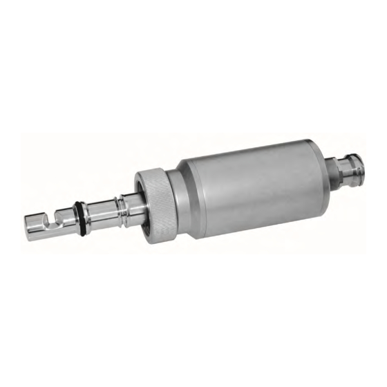
Page 13: Dimensions As56-F / As56-N Sensor
Lower O-ring groove (with approx. 60 mm port length) Upper O-ring groove (with approx. 30 mm port Swivel nut G 1-1/4" ISO 228/1 length) (short, approx. 19 mm) Orientation mark for measuring gap Probe head with optics and lamp module Airpurge connection - 9 - optek-Manual--1004-2011-02--AS56-US-2017-06-28 www.optek.com... -
Page 14: Accessories Weld-In Port As25
G1¼"A-ISO 228/1 Ø27mm [1.06"] Ø24.7mm [0.97"] Ø42mm [1.65"] G1¼"A-ISO 228/1 Ø27mm [1.06"] Ø25mm [0.98"] H7 G1¼"A-ISO 228/1 Ø27mm [1.06"] Ø25mm [0.98"] H7 Fig. 4: Weld-in port Weld-in port AS25-GS60 Weld-in port AS25-S60 Weld-in port AS25-G60 - 10 - optek-Manual--1004-2011-02--AS56-US-2017-06-28 www.optek.com... - Page 15 Technical data and exploded views Notice! After welding, distortion at the weld-in port has to be corrected! Modify the interior drill hole of Ø 24.7 mm to obtain the nominal diameter Ø 25 H7 (Ø 25.0 - Ø 25.021 mm) before installing the probe! - 11 - optek-Manual--1004-2011-02--AS56-US-2017-06-28 www.optek.com...
-
Page 16: Accessories Varivent Adapter Port As25-G60
The adapter allows sensor installation with Varivent inline housings. The adapter may be installed on all housings instead of a closing plate Ø 68 mm (2.68'') (TU no. 221-144.02, optek FH50-99). The adapter made of high-quality bulk material 1.4435 (SS 316 L) combines Varivent inline housings with the AS25-G60 weld-in port. -
Page 17: Accessories Clamp Adapter Port As25-G60
Tab. 3: Clamp adapter port AS25-G60 AS56 (L = 35 mm + OPL) [mm] insertion depth max. [mm] G1¼''A-ISO 228/1 Ø27mm [1.06"] Ø25mm [0.98"] H7 Ø30mm [1.18"] Ø56.5mm [2.22"] Ø63.9mm [2.52"] Fig. 6: Clamp 2.0" adapter port AS25-G60 - 13 - optek-Manual--1004-2011-02--AS56-US-2017-06-28 www.optek.com... -
Page 18: Accessories Optek T-Pieces For Pipe Din 11850
10 mbar - 16 bar for TS -40 °C / +120 °C (-40 °F / +248 °F) TS [°C] ≤ (248, 302, 392 °F) Admissible pressure at increased temperature PS [bar] Tab. 5: Dimensions for optek T-pieces for pipelines according to DIN 11850 Length Pipe size Inside Height Depth... -
Page 19: Accessories Optek T-Pieces For Pipe Od
10 mbar - 20 bar for TS -40 °C / +120 °C (-40 °F / +248 °F) TS [°C] ≤ (248, 302, 392 °F) Admissible pressure at increased temperature PS [bar] Tab. 7: Dimensions for optek T-pieces for pipe OD Length Pipe size Inside Height Depth... -
Page 20: Accessories Sealing Flange As25
O-ring is located 30 mm (1.18 '') higher. Both grooves are designed for O-rings Ø 18.64 x 3.53 mm. The swivel nut is designed for short threads G1-1/4'' ISO 228/1. Ø25mm [0.98"] Fig. 9: Sealing flange AS25 - 16 - optek-Manual--1004-2011-02--AS56-US-2017-06-28 www.optek.com... -
Page 21: Exploded View Of As56-F / As56-N Sensor
Measuring segment AS56, variable OPL Option: O-ring 18.64 x 3.53, EPDM, lower groove Option: O-ring 18.64 x 3.53, EPDM, upper groove Probe cable AS56 Screw M5 x 6 DIN 84 A4 Purge connection M5, Ms/Ni - 17 - optek-Manual--1004-2011-02--AS56-US-2017-06-28 www.optek.com... -
Page 22: Installation
/ removal of sensor impractical, poor cleanability 5. Avoid vertical installation from bottom, product may adhere to the windows, insertion / removal of sensor impractical, extremely poor cleanability due to port sump - 18 - optek-Manual--1004-2011-02--AS56-US-2017-06-28 www.optek.com... - Page 23 Appropriate lubricants are given in the spare parts list. • Do not exceed 25 bar during any pressure test. • Only remove a sealing flange if the pipeline is pressureless, cooled down and empty. The sealing flange is not suitable for safety ports. - 19 - optek-Manual--1004-2011-02--AS56-US-2017-06-28 www.optek.com...
-
Page 24: Installation Of The Sensor
Install only one O-ring. This way, you avoid creation of a hold-up volume or entrapment of process medium at the sensor. 3. Slide the O-ring into the lower or upper groove (see figure below). Fig. 12: O-ring in lower groove (left) or in upper groove (right) - 20 - optek-Manual--1004-2011-02--AS56-US-2017-06-28 www.optek.com... - Page 25 The probe may in no case touch the opposite wall, a 5 mm (0.20'') distance is sufficient. Observe opposite internals! 5. Slide the sensor into the weld-in port, adapter or T-piece. 6. Manually screw-tighten swivel nut. Fig. 13: Tightening swivel nut - 21 - optek-Manual--1004-2011-02--AS56-US-2017-06-28 www.optek.com...
-
Page 26: Airpurge
3. Reduce air pressure to approx. 0.1 bar (1.45 psi). 4. Retighten the cylinder nut (2). Keep up the gauge pressure. Air consumption in this operational state is minimal. - 22 - optek-Manual--1004-2011-02--AS56-US-2017-06-28 www.optek.com... -
Page 27: Wiring
Connecting sensor cable Notice! Exact information about the connection of a sensor to a converter is given in the instruction manual of the respective converter. There you can as well find the corresponding wiring plans. - 23 - optek-Manual--1004-2011-02--AS56-US-2017-06-28 www.optek.com... -
Page 28: Faults
"Software" in the instruction manual of the converter. Should you have any difficulty clearing the fault, feel free to contact our customer service. See chapter 11, page 37 for our contact data. - 24 - optek-Manual--1004-2011-02--AS56-US-2017-06-28 www.optek.com... - Page 29 Connected load > 600 ohms • Use appropriate mA-input. current results if measuring mA-signal (output) results are high. Compensation by adjusting Smaller deviations in the Poor calibration of the calibration of the sending % range receiving mA-input mA-output. - 25 - optek-Manual--1004-2011-02--AS56-US-2017-06-28 www.optek.com...
- Page 30 % range mA-output mA-input. Send system (converter and sensor) to optek for checking None of the above mentioned purposes. If necessary, the sensor Converter defective errors can be detected. body can remain in the pipeline so that only the optical arms and the converter have to be sent.
-
Page 31: Maintenance
Statistical service life is 3 years. Notice! The used detector is not subjected to measurable aging when used properly. - 27 - optek-Manual--1004-2011-02--AS56-US-2017-06-28 www.optek.com... -
Page 32: Exchange Of Lamp Module
Fig. 17: Loosening cylinder nuts and removing backplate 4. Carefully loosen the lamp and detector connectors. 5. Loosen both screws (1 in the figure below) of the lamp module. Fig. 18: Screws of lamp module - 28 - optek-Manual--1004-2011-02--AS56-US-2017-06-28 www.optek.com... - Page 33 9. Verify that the O-ring is provided on the backplate. Replace it if necessary. 10. Connect the 2-pin connector to the lamp module and the 3-pin connector to the detector. 11. Place the backplate on the housing, so that the drill holes correspond. - 29 - optek-Manual--1004-2011-02--AS56-US-2017-06-28 www.optek.com...
- Page 34 Maintenance 12. Fasten both cylinder nuts. Fig. 21: Placing backplate and fastening cylinder nuts 13. Re-connect the sensor cable. 14. Switch on the measuring system. 15. Follow the instructions given in chapter 9.3, page 31. - 30 - optek-Manual--1004-2011-02--AS56-US-2017-06-28 www.optek.com...
-
Page 35: Return To Operation After The Exchange Of Lamp Module
3. Check the system's zero-point (see instruction manual of the converter). 4. Document your settings using the form (see instruction manual of the converter). 5. Check the measuring results with regard to plausibility. 6. If the settings and measuring results are correct, enable measuring. - 31 - optek-Manual--1004-2011-02--AS56-US-2017-06-28 www.optek.com... -
Page 36: Spare Parts And Accessories
(FDA, USP Class VI) (FDA / USP Class VI) * Others on request. 9.4.5 Screw sets Tab. 14: Spare parts – screw sets Name / type Part number 4 x (0220-0111-00) Screw M2.5 x 10.8 DIN 84 1206-0004-0111-00 - 32 - optek-Manual--1004-2011-02--AS56-US-2017-06-28 www.optek.com... -
Page 37: Accessories - Cable Sets Stainless Steel Connector
40 m (131 ft) Cable Set AS16 040 m SS-1.5 1331-0200-0040-00 45 m (148 ft) Cable Set AS16 045 m SS-1.5 1331-0200-0045-00 50 m (164 ft) Cable Set AS16 050 m SS-1.5 1331-0200-0050-00 * Also applies to AS56. - 33 - optek-Manual--1004-2011-02--AS56-US-2017-06-28 www.optek.com... -
Page 38: Accessories - Process Adapter
Sealing flange AS25 for AS25-ports Material: 1.4435 (SS 316 L) Diameter: 25 mm Port AS25 1200-3401-0002- 00 O-ring groove for 30 and 60 mm port lengths sealing flange Port-gasket: O-ring 18.64 x 3.53 mm EPDM (FDA, USP Class VI) - 34 - optek-Manual--1004-2011-02--AS56-US-2017-06-28 www.optek.com... -
Page 39: Accessories - T-Piece For As16 / As56 - Din 11850
Accessories – T-piece for AS16 / AS56 - OD (BS 4825-1) Tab. 18: Accessories – T-piece - OD (BS 4825-1) Description optek T-piece for pipe OD (BS 4825-1) with port AS25-G60 (similar Ingold-port) Diameter inside: 25 mm (H7) for AS16 / AS56 / ASD25-N - Material: 1.4435 (SS 316 L) - Surface: electro-polished Ra <... -
Page 40: Eu Declaration Of Conformity
EU declaration of conformity EU declaration of conformity EU declaration of conformity Herewith we, optek-Danulat GmbH, Emscherbruchallee 2, 45356 Essen, Germany, declare in sole responsibility that the following measuring systems each comprising one converter of the series Control 4000 (C4XXX with X=0..6);... -
Page 41: Contacts
+1 800 371 4288 E-Mail: info@optek.de Fax: +1 262 437 3699 E-Mail: info@optek.com 中国 China 优培德在线测量设备(上海) optek-Danulat Shanghai Co., Ltd 有限公司 Room 718 Building 1 上海张江科苑路88 No. 88 Keyuan Road 号德国中心718 Pudong Zhangjiang 室 邮编:201203 Shanghai, China 201203 电话: +86-21-28986326...
Need help?
Do you have a question about the AS56 Series and is the answer not in the manual?
Questions and answers