
Related Manuals for Magnimage V4 Series


Summary of Contents for Magnimage V4 Series
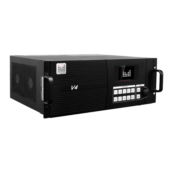
- Page 1 V4 multi-scene seamless switcher User manual △ Before using this LED Video Seamless Switcher,please read this manual carefully and preserved for reference in the future. MAGNIMAGE V4 series...
- Page 2 · · · · Statements Without the written permission, any unit or individual could not copy, reproduction or translate the book or part of it. Also could not transmit it in any form or any way(electronic, mechanical, photocopying, record or other way) for any business and profitable purpose.
-
Page 3: Table Of Contents
About Magnimage · · · · · · · · · · · · · · · · · · · · · · · · · · · · · · · · · · · · · · ·... - Page 4 · · · · · · · · · · · · · · · · · · · · · · · · · · · · · · · · · · · · · · · · · · · · · · · · · · · · · · · · · · · · · · · · · · · · · · · · · · · · · · · · · · · · · · · · 24 RONT PANEL INTRODUCTION MIG-H1 B ·...
-
Page 5: Briefs
Briefs Thanks for your purchasing our V4 multi-scene video switcher. Do hope you can enjoy the experience of the product performance. The design of the LED switcher conforms to international and industry standards. But if with improper operation, there will be a personal injury and property damage. In order to avoid the dangerous, please obey the relevant instructions when you install and operate the product. -
Page 6: Features
· · · · Features 2 main splicing output,single machine support 3840 x1080 Every single main output support 4 layers and 1 background Modify size and position of layers window randomly 1 multi-screen preview output,1 auxiliary preview output ... -
Page 7: Using Directions
Using directions Included Accessories MIG-V4 host accessories Using manual Certification USB DISK Power line×2 DVI line×2... - Page 8 · · · · MIG-H1 accessories Using manual Certificate Light×2 Flange edge×2 M4 screw×8 Power line Cross cable...
-
Page 9: Safety Tips
Safety Tips This product power supply input voltage range is from 110~240VAC, 50/60Hz, please use the correct power. Please make sure that all power cables are unplugged when connecting or disconnecting any signal lines or control lines. Make sure that all signal and power cables are unplugged when adding ... -
Page 10: Functions
· · · · Functions Overview MIG-V4 switcher is composed of MIG-V4 host and MIG-H1 console,single MIG-H1 can control up to 9MIG-V4 hosts. High-performance MIG-V4 host adopts advanced 12 bit algorithm,and it make picture more clear,delicate,colorful,ensure output signal synchronization and reducibility as well.Single machine supports output capability up to 3840*1080 pixels,and it supports 1 multi-screen preview and 1 auxiliary preview.It can realize 8 layers to 8 layers fade switching,the built-in matrix supports 12 inputs,and can expand 20 inputs with full live preview of all... -
Page 11: Rule Of Naming
Rule of naming MIG-V4 switcher is composed of MIG-V4 host and MIG-H1 console. Console Type:MIG-H1 3 basic host,the type as follow Host type Input port type MIG-V4-A 4VGA、4DVI、4SDI MIG-V4-B 4DVI、4DVI、4SDI MIG-V4-C 4HDMI、4DVI、4SDI MIG-V4-D 4DVI、2SDI、2VGA、4HDMI MIG-V4-E 8DVI、2SDI、2VGA MIG-V4-F 4DVI、6VGA、2SDI Host can add input expanding board to add the type and quantity of input port. -
Page 12: Technology Specification
· · · · Technology specification Input signal spec Ports Spec VESA VESA HDMI EIA/CEA-861,HDMI-1.3 480i、576i、720p、1080i/p(3G SDI) SDI VGA 2SDI input、 2VGA input Output signal spec Ports Resolution DVI(main output) 2×2 1920×1080/60Hz DVI(Multi-preview) 1×2 1920×1080/60Hz DVI(Auxiliary-Monitor) 1×2 1920×1080/60Hz Notes:2×2 represent 2 group of DVI,each group has 2 DVI ,which are copy effect. -
Page 13: Mig-V4 Front Panel Introduction
MIG-V4 front panel introduction Front panel introduction 1- Display screen:display current work state,inputinformation,electrical state etc. 2- Function buttons:realize appointed functions in special menu 3- Menu buttons:browse and set menu,includingconfirm,back and shortcut knob. -
Page 14: Rear Panel Introduction
· · · · Rear panel introduction 4- Standard Inputs Area: 12-channel inputs 5- Program 1: main output screen 1 port 6- Program 2: main output screen 2 port 7- Multi-screen preview:program output、preview output、 input signals real-time monitoring 8- Auxiliary preview: Full screen monitor any input signal 9-Multiple MIG-V4 host cascade splicing,frame lock plugs 10- RS232 control plug 11- USB plug: for upgrading... -
Page 15: Mig-V4 Card Introduction
MIG-V4 card introduction VGA input card Signal format VESA Ports 15 pin D-sub/mother ports Ports Qty. 4/input card VGA-A VGA-D VGA-B VGA-C DVI input card Signal format VESA Ports 24+5pin/mother ports Ports Qty. 4/input card HDMI input card Signal format EIA/CEA-861 HDMI-1.3 Ports HDMI Type A... - Page 16 · · · · SDI input card Signal format 480i、576i、720p、1080i/p(3G SDI) Ports SDI/mother ports Ports Qty. 4/input card SDIVGA 输入卡 信号规格 2SDI,2VGA VGA-B VGA-A DVI output card Signal format 1920×1080/60HZ Ports 24+5pin/mother ports Ports Qty. 4/input card(each 2 are coping effect) Control card Signal format Support sync signal,RS-232 and internet control port,USB...
-
Page 17: Mig-V4 Host Using Menu
MIG-V4 host using menu Using the menu of products is convenient to set,which meet user requirements,MIG-V4 host adopt a high brightness & contrast LCD screen to display the entire menu system.When the user does not have operation or operation timeout, the LCD screen will show the default state.If use the machine front button to set the machine,the LCD screen show the corresponding menu according to user operation,in order to prompt the user to operate better,faster and more intuitive . -
Page 18: Default State Introduction
· · · · Default state introduction After turning on the power of MIG-V4,the front panel screen display turn-on interface in the process of system start-up,afterit,the screen display current state,as showed below: Default state interface after turn-on: V4 MULTI-DISPLAY SWITCHER NONE NONE NONE... -
Page 19: Mig-V4 Main Menu
In the non-menu state,press OK button then enter the main menu state,the LCD screen will display as follow: Menu Status Info EDID Manage Misc Communication 语言菜单/Language Menu Input Config About Magnimage main menu sub-menu items,divided into pages display.Rotating”knob”to select above... -
Page 20: State Information Of Sub-Menu
· · · · State information of sub-menu Status Info Input Information Firmware Version Temperature & Fans Electric Report Input Information NONE NONE NONE NONE NONE NONE NONE NONE Reconfig Input List Display slot state every input Input information slot,ifalteration,you should read setting then set in this menu... - Page 21 Firmware Version A1529-F54D3 A1529-F0AC5-F0AC5 A1529-F34C9 A1529-F0AC5-F0AC5 A1515-F2511 A1529-F0BD1-F0BD1 A1529-FAAC5-F05CA V3-V005-201301 Electric report V OK A OK 0000 V OK A OK 0000 V OK A OK 0000 V OK A OK 0000 V OK A OK 0000 V OK A OK 0000 V OK A OK 0000 None None...
-
Page 22: The Sub-Menu Of Edid Management
· · · · The sub-menu of EDID management EDID Management 1:1-DVI A 1280x1024 60Hz 2:1-DVI B 1280x1024 60Hz 3:1-DVI C 1280x1024 60Hz 4:1-DVI D 1280x1024 60Hz 5:2-VGA A 1920x1080 60Hz 6:2-VGA B 1920x1080 60Hz 7:2-VGA C 1920x1080 60Hz 8:2-VGA D 1920x1080 60Hz Config EDID EDID Setting 1: 1-DVI A... -
Page 23: Misc Sun-Menu
Misc sun-menu Misc Auto Load Background LCD Test Pattern Factory Reset Set power on,if MIG-V4 host load background Auto Load Background automatically LCD Test Pattern Test the LCD screen of V4 host Factory Reset Reset factory default setting If user turn on “Auto Load Background“,MIG-V4 will load stored background when power on every time, boot time get longer,after waiting for completion of loading,then continuing other operations. -
Page 24: Sub-Menu Of Communication Setting
· · · · Sub-menu of communication setting Communication IP Address 192.168.1.223 Subnet Mask 255.255.255.0 Apply Setting Cancel Reset IP address Default state:192.168.1.223 Subnet mask Default state:255.255.255.0 Before applying,modify internet Apply setting parameter,after confirming then Communication back to previous menu Cancel the change of IP and Cancel subnet... -
Page 25: Languange/菜单语言
Languange/菜单语言 菜单语言/Language English 简体中文 繁軆中文 English Set the menu system language to English 简体中文 Set the menu system language to simply Chinese 繁体中文 Set the menu system language to Chinese... -
Page 26: Input Ports Setting Sub-Menu
· · · · Input ports setting sub-menu Input ports setting INPUT 1 DVI A DVI A DVI A DVI A INPUT 2 VGA A VGA A VGA A VGA A INPUT 3 HDMI A HDMI A HDMI A HDMI A INPUT 4 INPUT 5 INPUT 6... -
Page 27: About Magnimage
About Magnimage About Magnimage http://www.magnimage.com/cn/ Website http://www.magnimage.com/cn/ Wechat (Chinese) ID:Magnimage Wechat (English) ID:Magnimage-ENG... -
Page 28: Mig-H1 Front&Rear Panel Introduction
· · · · MIG-H1 front&rear panel introduction Front panel introduction 3 Adjustment area 1 screen and menu setting 2witch mode option 12 Destinations area 4 Preset editing 11 Presets area 10 Output screen 9 layers area 8 Input area 7 Group area 5 Transition area 6 Function area... - Page 29 1 Display screen and menu setting Control cursor move up and down Enter or exit menu In special menu,realize appointed functions The port of light Connect light...
- Page 30 · · · · Switch between main 2 Switch mode option area output and preview Copy between main output and preview The same between main Above switch modes output and preview,if are combined button, modify preview,main SHIFT+corresponding output will change 3Adjustment area oystick:...
- Page 31 4Preset editing area Copy+number key in preset area, copy preset,for example choose preset 1,then press Copy,press Copy+2, and 1 preset be copied to preset 2; Long press Save+number key in preset area,store the preset to number key Load key+number key in preset area,...
- Page 32 · · · · Devided the units of 5Transition area MIG-V4 into group lighted group key,every MIG-V4 of group switch together Take prepared:the key light on means switch Lighted,lock all operation buttons in available,only in the transition area “lock”state,TAKE PREPARED key light T-Bar,pressagain, off,switch operation is clear lock...
- Page 33 6 Function area Top:top the current layers Bottom : bottom the Clear all layers current layers Choose Capture background, background of capture main output MIG-V4,every main picture output can store 3 Call color key menu background rapidly,realize text overlay, cut picture Choose pure background of VGA adjustment menu,...
- Page 34 · · · · 10Output screen area 7Group area 1,2 correspond main Group MIG-V4 that control ba output 1 and 2 same H1,maximum 4 groups; 当 前 选 择 的 为 红 黄 交 current option group light 替 flicker 9layers area The button of 1 to8 correspond 8 layers,Clear layer+number button:clear current layer;...
- Page 35 12Destinations area According to the IP scanning from the MIG - V4 , determine each key to corresponding MIG - V4; each MIG-H1 maximum controls 9 MIG-V4 at the same time,the corresponding button lamp to red. The currently selected MIG - V4 button is red-yellow flashing. 11Presets Each key corresponds to anative template.
-
Page 36: Mig-H1 Back Panel Introduction
· · · · MIG-H1 Back Panel Introduction LAN port,can link to MIG-V4 via LAN reserve RS232 control USB port, can upgrade MIG-H1; store port or read preset file through USB flash disk;Import BMP format high definition background image into MIG-V4 Light switch MIG-H1 switch... -
Page 37: Mig-H1 Console Usage Menu
MIG-H1 Console Usage Menu Using the menu system of product can set conveniently and intuitively to meet customer requirements. MIG-H1 console adopts a LCD with high-brightness and high-contrast to display the whole menu.LCD screen willdisplay non-menu under the condition of users without operating or timeout. -
Page 38: Mig-H1 Main Menu Introduction
· · · · Green flashing when MIG-H1console connected with MIG-V4 mainframe, otherwise red flashing Corresponding IP will be displayed when MIG-H1 Dest[1] console connected with MIG-V4 mainframe,otherwise display ‘Wait Connected’ MIG-H1 Main Menu Introduction Menu INPUT OUTPUT LAYER MISC PRESETS BACKGROUND CONFIG GROUP T-BAR SETTING... -
Page 39: Inputsetting Sub Menu
The main menu has ten sub menu items, divided into two pages display.Through prompting, selectbutton of the display perimeter to enter or return to menu and the cursor moves up and down. InputSetting Sub Menu INPUT SRC.1[NONE] Brightness Contrast Image Crop EDID VGA Adjustment Return... -
Page 40: Output Setting Sub Menu
· · · · Brightness The range of 0-256 Contrast The range of 0-256 Afterintercepting input signal, according to the current layer Image crop set the function of the output to the screen EDID Customized input resolution Automatically adjusts the display position of theVGA input adjustment image Output Setting Sub Menu... - Page 41 Brightness The range of 0-256 Contrast The range of 0-256 Canset respectively twogroups main output channel Output area switched on or off, the horizontal and vertical position, can settings overlay. Edge Blending Cfg. Edge Blending Cfg. Screen1 Blending Setting Screen1 Blending Setting Return RESET Screen1 Blending Setting...
-
Page 42: Layer Sub Menu
· · · · Edge blending Settings: Each main output channel can open edge blending function according to user’s actual usage, set the horizontal/vertical starting of fusion and the horizontal size/vertical height of fusion. Gamma choice: adjust Gamma curve of fusion zone The choice of fusion direction is: the direction from dark to light (the direction of transparency gradient from 0to 100%) Customized curve: user-defined Gamma curve... -
Page 43: Misc Sub Menu
Misc Sub Menu Misc SET Communication Tbar And Jointed Arm Set USB Operate Factory Reset Return Enter Communication Located IP Set Destinations Connected Information Return Enter Set IP;inquire destinations connection information... - Page 44 · · · · Tbar And Joined Arm Set Tbar Set Joined Arm Set Return Enter Factory Reset Reset V2/3/4 Reset H1/H2 Return Enter Tbra& joystick Adjust respectively Tbar and joystick setting Import BMP format high definition background image into U disk MIG-V4 mainframe from U disk;...
-
Page 45: Preset Sub Menu
Preset Sub Menu Preset Presets U-Disk Operation Clear All Presets Return Enter Presets U-Disk Operation Save All Presets Read All Presets Preset U-Disk Operation Return Enter Preset U-disk operation choose to save the presets that user ’s stored to the U disk Load the preset file that in U disk into H1 console;... -
Page 46: Background Setting Sub Menu
· · · · Background setting sub menu Background Config Load All Background Switch All To Background Color Background Management Background Capture Return Enter Background Capture Save Captured Background In: Background1 Background2 Background3 Capture Picture In Program Screen! Return Start Load all backgroundload all background image stored in native machine, it will prompt completion when progress bar is 100% Switch all to background colortwo groups of main output both switch to... - Page 47 Background Management Output/Screen 1 Output/Screen 2 Return Enter 背景设置 Prog.Screen 1 Background1 Background2 Background3 Background Color Return LOAD Edit Load all backgroundload all background image stored in native machine, it will prompt completion when progress bar is 100% Switch all to background color two groups of main output both switch to pure color background Background management:can manage respectively the background image of output 1 and 2;”LOAD”invoke stored...
-
Page 48: Group T-Bar Sub Menu
· · · · GROUP T-BAR Sub Menu GROUP T-BAR Setting LOCAL IP:192.168.1.110 Dest.[1]IP:192.168.1.233 Dest.[2]Not Connected Dest.[3]Not Connected Dest.[4]Not Connected Dest.[5]Not Connected Dest.[6]Not Connected Dest.[7]Not Connected Dest.[8]Not Connected Add To Del From Return Enter Group Group It can group MIG-V4 mainframe controlled by the same MIG-H1. It can add or delete grouping selected MIG-V4, but can be divided into four groups at most. -
Page 49: Time Task Sub Menu
Time Task Sub Menu TIME&TASKS Time Task Clear All Tasks Return Enter Task Set Page1/16 Take[1]None Take[2]None Take[3]None Edit Take[4]None Take[5]None Del. Take[6]None Take[7]None Take[8]None Page Return Rank Page Up Down Date Set time and date Users can sort storage of the preset and directly press Tasks “NEXT”to next preset task;... -
Page 50: Color Key Sub Menu
· · · · Color key Sub Menu Color Keyer Pixel H Position 3030 Pixel H Position Color Key Red Range Green Range Blue Range Color Keyer Useful On the Top Displayed Layer! Recall Return Pos. Using a joystick choose the color of the need to remove by controlling cursor up and down and move around and then press “ON“... -
Page 51: Language Sub Menu
Language Sub Menu 菜单语言/LANGUAGE English 中文简体 中文繁体 Return Enter English The Menu will display in English 简体中文 The Menu will display in simplified Chinese 繁体中文 The Menu will display in traditional Chinese... -
Page 52: Warning
· · · · Warning MIG-V4 is not related to the function of operation on its display interface, while it can browse input information, electrical state and communication, etc. Single MIG-V4 must use a crossover cable when it connected with MIG-H1 via LAN;... -
Page 53: The Warranty Provisions
Warranty Explanation Whole Unit Warranty Period Three years (from the buying date); If the invoice is lost, the 60 days after the production date will be the warranty start date for the product. The warranty provisions Immersion in water, collision, blots and scratch on surface after use, or ...
Need help?
Do you have a question about the V4 Series and is the answer not in the manual?
Questions and answers