Table of Contents
Advertisement
Advertisement
Table of Contents

Subscribe to Our Youtube Channel
Related Manuals for Life Fitness Optima Plus Flexibility Stretch


Summary of Contents for Life Fitness Optima Plus Flexibility Stretch
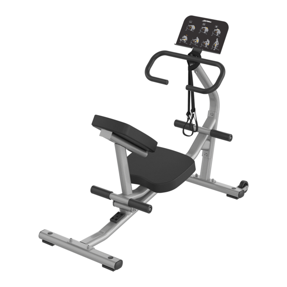
- Page 1 Optima Plus Flexibility Stretch OP-FS Owner's Manual 1012508-0001 REV AA...
- Page 3 Latin America and Caribbean* Spain Hong Kong Life Fitness, Inc. Life Fitness IBERIA Life Fitness Asia Pacific LTD Columbia Centre III C/Frederic Mompou 5,1º1ª 32/F, Global Trade Square 9525 West Bryn Mawr Avenue 08960 Sant Just Desvern Barcelona 21 Wong Chuk Hang Road Rosemont, IL 60018 U.S.A.
- Page 4 User and Service Documents Link https://www.lftechsupport.com/web/document-library/documents Additional information is available online using the link above. أ علاه إل ر إبط باستخدإم إ لإ ن تر نت على إضافية معلومات تتوفر 点击上面的链接可在线获取更多信息。 Flere oplysninger er tilgængelige online gennem linket ovenfor. Bijkomende informatie is online beschikbaar via bovenstaande link. Vous trouverez plus d'informations en ligne à...
-
Page 5: Table Of Contents
2XL Corporation. PureGreen 24 is a trademark of Pure Green. © Copyright 2019, Life Fitness, LLC. All Rights Reserved. Life Fitness, Hammer Strength, Cybex, ICG and SCIFIT are registered trademarks of Life Fitness, LLC and its affiliated companies and subsidiaries. Brunswick and related trademarks used under license from Brunswick Corporation. -
Page 6: Safety Information
Safety Information It is the sole responsibility of the purchaser of LIFE FITNESS products to read the owner’s manual and warning labels and instruct all individuals, whether they are the end user or supervising personnel, on proper usage of the equipment. - Page 7 • Ensure that any person(s) making adjustments or performing maintenance or repair of any kind is qualified to do so. LIFE FITNESS will provide service and maintenance training at our corporate facility upon request or in the field if proper arrangements are made.
-
Page 8: Product Labels
Product Labels General Warning Pinch Hazard Do Not Sit Serial Number Page 6 of 22... -
Page 9: Label Locations
Label Locations Item Description Qty. General Warning Pinch Hazard Serial Number Do Not Sit Placard Page 7 of 22... -
Page 10: Assembly
2. Assembly Component and Hardware List Components Item Description Qty. Base Frame Seat Frame Front Upright Front Support Rear Support Handle Placard Plate Seat Pad Chair Pad Wrist Strap Hardware Item Description Qty. Hardware Pack, OP-FS-HDWR M10 Hex Nylock Nut 3/8"... -
Page 11: Tools Required
Tools Required • 17 mm Socket wrench • 8 mm Allen wrench • Torque wrench • Rubber mallet Assembly Procedure Assemble Frame Install bolts, washers, and hex nuts securing rear support to base frame using an 8mm Allen wrench and a 17mm socket wrench. - Page 12 Install bolts, washers, and hex nuts securing front upright to base frame using an 8mm Allen wrench and a 17mm socket wrench. Item Description Qty. Base Frame Front Upright M10 x 25mm Bolt 3/8" Flat Washer M10 Hex Nylock Nut Hole Plug Tighten bolts to 20-25 ft-lb (27-33 Nm).
- Page 13 Place the handle through the wrist strap loop. Install bolts, washers, and hex nuts securing handle to front upright using an 8mm Allen wrench and a 17mm socket wrench. Item Description Qty. Front Upright Handle Wrist Strap M10 x 60mm Bolt 3/8"...
- Page 14 Install Pads Install bolts and washers securing chair pad to seat frame using an 8mm Allen wrench. Item Description Qty. Seat Frame Chair Pad 3/8" Flat Washer M10 x 30mm Bolt Tighten bolts to 40-50 in-lb (4.5-5.5 Nm). Install bolts and washers securing seat pad to seat frame using an 8mm Allen wrench. Item Description Qty.
-
Page 15: Product Information Specifications
3. Product Information Specifications Machine Weight: 78 lbs. 35 kg. Size (L x W x H): in. = 54 x 23 x 43 cm = 137 x 58 x 109 Live Area (L x W): in. = 78 x 59 cm = 198 x 150 Max User Weight: 300 lbs. -
Page 16: Exercise
4. Exercise General Exercise Information Intended Use The intended commercial use of this machine is to aid exercise and improve general physical fitness. Prior to Exercise Prior to starting a training program, get a complete physical exam to make sure your physician agrees that you are ready. -
Page 17: Maintenance Procedures
5. Maintenance Procedures Maintenance Schedule ACTION DAILY WEEKLY MONTHLY AS NEEDED CLEAN Upholstery Hand Grips Frames INSPECT Paint Hardware Frame Hand Grips Clean • Upholstery with an approved or compatible cleaner. • Hand grips with an approved or compatible cleaner. •... - Page 18 Gym Wipes are large, durable pre-moistened wipes to use on the equipment before and after workouts. Use Gym Wipes on the equipment for at least 2 minutes for general disinfection purposes. Contact Customer Support Services to order these cleaners (1-800-351-3737 or email: customersupport@lifefitness.com).
-
Page 19: Warranty
Who Pays Transportation and Insurance For Service If the Product or any covered part must be returned to a service facility for repairs, We, Life Fitness, will pay all transportation and insurance charges for the first year. You are responsible for transportation and insurance charge after the first year. -
Page 20: Warranty Coverage
Warranty Coverage NOTE: There is no warranty coverage for labor on Strength Products. Item 10 Years 5 Years 1 Year 90 Days Frame Grips Upholstery Hardware / Mechanical Items Not Specified Page 18 of 22... -
Page 21: Bolt To Floor Guidelines
7. Bolt to Floor Guidelines Introduction LIFE FITNESS designs its products to be stable when used as designed. Because strength training is dynamic, we cannot predict how users will ultimately use the products in all circumstances. Therefore, LIFE FITNESS recommends that strength training equipment be secured to a solid, level surface to stabilize and eliminate rocking or tipping over. -
Page 22: Anchor Types
3000psi (20 N/mm2) beyond anchor length Pullout Force LIFE FITNESS specifies Hilti ™ static and dynamic anchors. According to the anchor manufacturer, the recommended design pullout force (in tension) for the specified anchors, when properly installed in cracked concrete, is provided in the side table. -
Page 23: Static Anchor Procedure
• Vacuum (for debris) Static Anchor Procedure CAUTION: If it is possible that the length of your bolt will not provide the minimum requirement of 2.5” (63.5mm) of engagement, a longer anchor should be used. Place unit into position to be mounted and cycle unit to set stance. Each foot must get at least one static fastener. -
Page 24: Foot Dimensions
Foot Dimensions Use below image to determine foot specifications. Page 22 of 22...
Need help?
Do you have a question about the Optima Plus Flexibility Stretch and is the answer not in the manual?
Questions and answers