
Related Manuals for GasTech D-Guard


Summary of Contents for GasTech D-Guard
- Page 1 D‐Guard Digital Guard Intrinsically Safe Intelligent Gas Detector Part Number 65‐1010xxx Manual Revision v2.08 (updated 5 June 2009) ...
-
Page 3: Table Of Contents
Table of Contents Introduction ............................... 6 Features ..............................6 Installation ..............................7 Mounting .............................. 7 Opening The Enclosure ......................... 8 Wiring ..............................10 2.3.1 Connection to Controller ......................10 2.3.2 Connection to Barriers......................... 11 2.3.3 Optional Relay Board ........................14 Operation............................17 Advanced Setup............................18 Changing the PCB or Sensor ........................ 18 PCB Jumpers and Calibration....................... 22 3.2.1 Isolate Mode.......................... - Page 4 DISCLAIMER Under no circumstances will GasTech Australia be liable for any claims, losses, or damages resulting from or arising out of the repair or modification of the equipment by a party other than GasTech Australia or its authorised service representatives, or by operation or use of the equipment other than in accordance with the printed instructions provided by GasTech Australia or if the equipment has been improperly maintained or subject to neglect or accident. Any of the foregoing will void the warranty. ...
- Page 5 Enclose the copy of your contact details. Pack the instrument and all its accessories (preferably in its original packing) and any special instructions. Repairs are warranted for 90 days from the date of shipment. Sensors have individual warranties. Always include your address, purchase order number, shipping and billing information, and a description of the defect as you perceive it. If this is the first time you are dealing directly with the factory, you will be asked to provide credit references, prepay, or authorise COD shipment. NOTE: GasTech Australia assumes no liability for work performed by unauthorised service facilities. Page 3 © 2008 Gastech Australia Pty Ltd ...
- Page 6 WARRANTY STATEMENT 1. Consumers have the benefit of conditions and warranties implied by the Trade Practices Act 1974 (TPA) and similar provisions of State and Territory enactments and nothing in these conditions is intended to exclude, restrict or modify any statutory obligation of GASTECH AUSTRALIA PTY LTD (Company) if that cannot lawfully be effected. 2. This warranty relates only to Equipment manufactured and services supplied by the Company, its related corporations and subsidiaries. Equipment or any part thereof which is returned to the Company, ...
- Page 7 Page 5 © 2008 Gastech Australia Pty Ltd ...
-
Page 8: Introduction
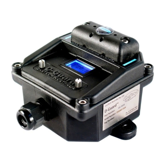
Introduction GasTech Australia is proud to introduce the next step in fixed gas detection equipment. The D‐Guard (Digital Guard) is an intelligent gas detector which is designed around the operators requirements. Easy to calibrate, easy to set up, and highly stable, fixed‐point toxic and Oxygen gas detector. The D‐Guard is an industry standard two wire 24VDC 4‐20mA device. 1.1 Features • Non intrusive calibration • No alarms during calibration • One PCB card for all gases detected • No tool calibration • Sensor drift elimination program • Long‐term sensor deteriation drift elimination program • Permanent back light • Fail‐safe mode • Non corrosive housing • High impact housing • Splashguard standard supply • IP66 design • IEC EX ia IIC T4 © 2008 Gastech Australia Pty Ltd Page 6 ... -
Page 9: Installation
NOTE: The packing slip indicates the serial number of your D‐Guard . The serial number is also on a label on the side of the D‐Guard . Please record the serial number on the front of this manual. The installation should be in the area with most potential to detect the gas as quickly as possible. Take note of the gas density as this will help in finding the best location for the D‐Guard . For example, heavier gases like S would have the sensor mounted lower than for Hydrogen which is a lighter gas. Securely mount the unit to the wall using wall plugs and screws. Dimensions of the two mounting holes on the D‐Guard enclosure are shown below. Page 7 © 2008 Gastech Australia Pty Ltd ... -
Page 10: Opening The Enclosure
2.2 Opening The Enclosure In order for power to be connected inside the unit, the enclosure must be opened. 1. Remove the 4 housing lid screws (4mm Alan key). The screws are held in with “O” rings to stop them falling out and losing them. 4mm Hex or Allan Key screws 2. Gently remove the lid making sure that you don’t lose the 4 lid screws or the large “O” ring that seals the lid to the base. Screw retaining “O” ring 3. Turn over the lid to find the green power connector. Power connector © 2008 Gastech Australia Pty Ltd Page 8 ... - Page 11 Housing “O” ring seal 6. Fit lid and tighten the 4 screws using a 4mm Allan key tightening the housing evenly. Page 9 © 2008 Gastech Australia Pty Ltd ...
-
Page 12: Wiring
2.3 Wiring The D‐Guard sensor can be used with any standard 2 wire, 4 to 20 mA 24VDC controller. Typical controllers include the GasTech Australia Micro Rack . Located on the PCB, bottom right corner there is a two pin removable plug. Ensure the positive and negative wires are terminated with the correct polarity, which is marked on the PCB. Removable 2‐pin plug. 0VDC and +24VDC 2.3.1 Connection to Controller When connecting a D‐Guard unit to a controller such as the GasTech 4100R controller, follow the pinouts as outlined below. Other third party controllers are also connected in the same manner. © 2008 Gastech Australia Pty Ltd Page 10 ... -
Page 13: Connection To Barriers
The barriers designed to protect the system must be mounted outside of the hazardous area in an area designated as Non‐hazardous or safe in which the hazard is not and will not be present. If you are utilizing the D‐Guard in a Hazardous environment, you will need to select an appropriate IS barrier. Selection of the type of barrier requires consideration of the voltage drops that occur in the system. As the D‐ Guard requires a minimum of 12VDC to operate, the voltage drops in the barrier system, controller load resistor and cabling cannot exceed the power supply voltage less 12VDC. WARNING: Installers should consult the Intrinsically Safe Barrier manufacture and refer to IEC Intrinsically Safe System Standard IEC 60079‐25:2003 or AS/NZS 60079.25:2004 before selecting a suitable barrier. A D‐Guard operated without a barrier will require the D‐Guard to be inspected by the manufacture to confirm that none of the safety components have been damaged. Page 11 © 2008 Gastech Australia Pty Ltd ... - Page 14 GasTech recommend the GasTech 57‐9010‐02 barrier (KFD2‐STC4‐Ex1) for most systems. This barrier will work on all controllers at 24VDC. Wiring of the GasTech 57‐9010‐02 barrier is as follows: © 2008 Gastech Australia Pty Ltd Page 12 ...
- Page 15 A second barrier that can be used is the GasTech 57‐9010‐01 (MTL 7787+). This barrier must only be used in conjunction with the GasTech 4100R controller card, as the 4100R card has 100Ω load. WARNING: If you use this barrier on another controller that uses a load above 100Ohms the D‐Guard will turn off when it see a high gas reading (>15mA) as the volt drop over this barrier is greater. Wiring of the GasTech 57‐9010‐01 barrier is as follows: Page 13 © 2008 Gastech Australia Pty Ltd ...
-
Page 16: Optional Relay Board
main PCB. Current source loop output, for connection to an external controller FB (feedback) Connect this to negative side of the power supply This needs to be connected to the + connector on the D‐Guard main PCB. This needs to be connected to the ‐ connector on the D‐Guard main PCB. DG‐ This relay is energized when AL1 is active. This alarm point is adjustable in software as AL1 Low Alarm described in the next section. This relay is energized when AL2 is active. This alarm point is adjustable in software as AL2 High Alarm described in the next section. This relay is normally energized. It becomes de‐energized when there is a sensor Fault Relay failure, power failure or when the D‐Guard is in Isolate mode. This jumper connects the FB and 0V lines together. It allows the D‐Guard main PCB Jumper to operate in standalone mode where a system controller is not present © 2008 Gastech Australia Pty Ltd Page 14 ... - Page 17 CAUTION: The relay contacts are rated at 5A @ 48VDC max. Mains connection is not permitted. TM The D‐Guard with relay option is normally used in standalone mode, however it can still be connected back to a controller such as the Gastech 4100R. The diagram below shows how the units are wired together. NOTE: In this configuration, the jumper on the relay PCB must be removed. Internal Connection diagrams: D-Guard to Relay Board Connections (Current loop output configuration) REMOVE Lk1 (Do not insert) Connect to +24VDC Page 15 © 2008 Gastech Australia Pty Ltd ...
- Page 18 D-Guard to Relay Board Connections (Standalone configuration) Lk1 MUST BE INSERTED Connect to +24VDC Connect to 0VDC © 2008 Gastech Australia Pty Ltd Page 16 ...
-
Page 19: Operation
NOTE: The D‐Guard starts up in a warm‐up Isolated mode with the mA locked at 3mA for 90 seconds while the sensor stabilised and the D‐Guard program initialises and completes a series of function tests. After the start up procedure and all tests are completed if operating is within tolerance the display will go into normal operating mode, the mA will be released and the system will then be functioning. The LCD screen shows the status of the system. Gas reading Gas being detected Unit of measurement Full scale value Page 17 © 2008 Gastech Australia Pty Ltd ... -
Page 20: Advanced Setup
3.1 Changing the PCB or Sensor 1. Isolate the sensor back at the control panel so an open circuit fault will not trip or create any alarms. 2. Remove the 4 housing lid screws (4mm Alan key). The screws are held in with “O” rings to stop them falling out and losing them. 4mm Hex or Allan Key screws 3. Gently remove the lid making sure that you don’t lose the 4 lid screws or the Large “O” ring that seals the lid to the base. Screw retaining “O” ring © 2008 Gastech Australia Pty Ltd Page 18 ... - Page 21 4. Turn over the lid and remove the green power connector and the D‐Guard will power down. The display will go blank and the back light will turn off. Power connector 5. Move to a clean location 6. Gently remove the 4 Phillips head screws holding the PCB in place PCB mounting screws 7. Gently remove the PCB which will expose the sensor. Page 19 © 2008 Gastech Australia Pty Ltd ...
- Page 22 9. If you are replacing the sensor, remove the old sensor and plug in the new one. Confirm the new sensor is the same as the old sensor. Different sensor connection pins 10. Gently press the new sensor back into place. 11. If replacing a sensor, you should also replace the sensor filter and gasket at the same time. 12. The sensor filter and gasket need to be ordered separately to the sensor. Note: The sensor filter part number is 33‐9998 and the gasket part number is 07‐1010‐01 © 2008 Gastech Australia Pty Ltd Page 20 ...
- Page 23 Gasket Filter 13. Remove the old gasket with a small screw driver. The gasket has double‐sided tape holding the filter and gasket in place. Filter and gasket location 14. Fit new gasket and filter the same way as previously fitted. Use the sticky side to stick to the plastic enclosure. Filter fitted to the gasket before installation to housing 15. Gently fit the PCB with new sensor back onto the lid and gently tighten the 4 Phillips head screws until the PCB comes flush with the mounting posts. 16. If you have just replaced the PCB, or have replaced the sensor with a different model, skip to the next section as the PCB may need some jumper or calibration settings changed. 17. If you are replacing the sensor with the exact same model as previous, the enclosure can be screwed back together as follows Page 21 © 2008 Gastech Australia Pty Ltd ...
-
Page 24: Pcb Jumpers And Calibration
First, open the calibration plate by unscrewing the two thumb screws on the calibration plate. Note: The plate is designed to pivot on the left screw. The screws are different length and will stay connected to the plate. The screws are captive to the plate but can be fully removed. Don’t fully remove the screws as you may lose them. Isolate switch in the non‐isolated position © 2008 Gastech Australia Pty Ltd Page 22 ... -
Page 25: Normal/Invert Jumper
Gas Sensor Model GasTech Part Number Chlorine 4CL 65‐8009‐4CL 7CLH 65‐8009‐7CLH Nitrogen Dioxide 4ND 65‐8004‐4ND 7NDH 65‐8004‐7NDH Ozone 7OZ 65‐8005‐7OZ Chlorine Cl2 3E 10/50 65‐9097‐CL2‐1 65‐9097‐CL2‐2 Chlorine Dioxide ClO2 3E 1 65‐9097‐CL02 Fluorine F2 3E 1 65‐9097‐F2 Hydrogen Fluoride HF 3E 10 & HF 3E 10S 65‐9097‐HF Nitrogen Dioxide NO2 3E 50 65‐9097‐NO2 Ozone O3 3E 1 65‐9097‐O3‐2 Page 23 © 2008 Gastech Australia Pty Ltd ... -
Page 26: Sensor Bias Jumper
Inverted signal jumper Jumper in inverted position 3.2.3 Sensor Bias Jumper This jumper should be in the off position for all sensors, except sensors needing a Bias voltage. The table below lists some common sensors that require a bias voltage. If you are replacing a sensor for a different gas, the bias voltage may need to be adjusted by the adjustment pot as described next. Sensor Model Bias Voltage GasTech Part Number HCL 7HL 300mV 65‐8011‐7HL NO 4NT 300mV 65‐8002‐4NT NO 7NT 300mV 65‐8002‐7NT ETO 7ETO 300mV 65‐8013‐7ETO HCL 3E 30 200mV 65‐9097‐HCL/HBR NO 3E 100 200mV 65‐9097‐NO THT 3E 100 150mV 65‐9097‐THT © 2008 Gastech Australia Pty Ltd Page 24 ... -
Page 27: Sensor Bias Voltage Adjustment Trimpot
Sensor bias jumper Sensor bias jumper in off position 3.2.4 Sensor Bias Voltage Adjustment Trimpot CAUTION: This trimpot is set by the factory on delivery. Do not adjust it as it can burn out the sensor and void warranty. If you are setting up the board for a different sensor that needs to adjust the bias voltage please contact the factory before hand to confirm the procedure. 1. Measure the millivolts across the reference and sensing sockets on the PCB as shown below. 2. Adjust the Bias trimpot to the required Bias voltage. 3. The Bias jumper must be in the “On” position and the shorting link must be removed. Page 25 © 2008 Gastech Australia Pty Ltd ... -
Page 28: Shorting Link Jumper
Reference Sensing Sensor Bias voltage adjustment pot 3.2.5 Shorting Link Jumper The shorting link will be installed on all non bias sensors. Shorting link jumper Shorting link jumper installed © 2008 Gastech Australia Pty Ltd Page 26 ... -
Page 29: Display Current Calibration Trimpot
3.2.6 Display Current Calibration Trimpot This trimpot is factory set and should not need adjusting. See the Appendix for more information. Display current calibration 3.2.7 Oxygen Load Jumper This jumper is only applicable for an Oxygen sensor. It will be in the down position for an Oxygen sensor and up for all other sensors. Oxygen load jumper Load jumper in Oxygen mode Page 27 © 2008 Gastech Australia Pty Ltd ... -
Page 30: Software Configuration And Calibration
The table below shows the settings for the various GasTech oxygen sensors. Sensor GasTech Part Normal Invert Shorting Oxygen Load Sensor Bias 0‐25% Range Number Jumper (J2) Link (J3) Jumper (J4) Jumper (J6) Gain Setting 7OX (V) 65‐8000‐7OXV Invert Off Oxygen Off G 3 4OX (1) 65‐8000‐4OX1 Invert Off Oxygen Off G 3 4OX (2) 65‐8000‐4OX2 Invert Off Oxygen Off G 5 3.3 Software Configuration and Calibration 3.3.1 Configuration ... - Page 31 20.0 10.0 ppm 8 NO 100 25 75 100 50 ppm 6 NO2 20.0 2.0 5.0 20.0 10 ppm 8 HCN 100 4.7 10.0 99.9 10 ppm 11 H2S 100 10 15 100 25 ppm 3 Page 29 © 2008 Gastech Australia Pty Ltd ...
- Page 32 12. If alarms are turned on, the next menu will prompt for a value at which alarm 1 (low) will be activated. Use the “Up” or “Down” button to change the value and the “Select” button to move to the next digit. Repeat this procedure until the value is set and then press the “Select” button to move to the next menu. 13. If alarms are turned on, the next menu will prompt for a value at which alarm 2 (high) will be activated. Use the “Up” or “Down” button to change the value and the “Select” button to move to the © 2008 Gastech Australia Pty Ltd Page 30 ...
- Page 33 15. The next screen is used to set the gain for the sensor. Use the “Up” or “Down” button to set the correct gain value. 16. Another way of determining the required gain is to look up the sensor sensitivity/output current from the manufacturer’s specification datasheet. Multiply the sensor output by the range of the detector. This will provide you with the “Calculated Full Scale Sensor Output”. Establish the correct gain setting using the table below. Gain Setting Factory Setup (Calculated Full Scale Sensor Output) G 0 750 – 440 uA G 1 440 – 290 uA G 2 290 – 180 uA G 3 180 – 130 uA G 4 130 – 85 uA G 5 85 – 60 uA G 6 60 – 40 uA G 7 40 – 25 uA G 8 25 – 17 uA G 9 17 – 11 uA G 10 11 – 7.0 uA Page 31 © 2008 Gastech Australia Pty Ltd ...
- Page 34 20. The next screen will depend on the type of gas the D‐Guard is setup to detect. If the unit is configured for O , the menu will show autospan, for all other gases the menu will show autoz. This Atmospheric compensation menu is one of the most advanced features of the D‐GuardTM. This logic monitors the sensor over a given time and calculates against a pre determined criteria which will then adjust the sensors base line to keep the sensor in accurate calibration and eliminate sensor drift which is a characteristic of all electrochemical sensors as they age. This feature prevents false alarms from drifting older sensors. Use the “Up” or “Down” button to enable or disable this feature. Press the “Select” button to move to the next menu. © 2008 Gastech Australia Pty Ltd Page 32 ...
-
Page 35: Calibration
Shorter intervals might be recommended depending on selected sensor. WARNING: The gas detection equipment is a safety system designed to protect your life and the plant operations. Not calibrating or extending the calibration intervals to save costs, could have a detrimental effect on the accuracy of the system as sensors might not respond. Page 33 © 2008 Gastech Australia Pty Ltd ... - Page 36 If the splash guard is fitted this will need to be removed so you can apply the gas directly to the sensor. Remove the splash guard by removing the two screws (4mm Alan key). The calibration procedure is dependent on whether the sensor is a: 1. Oxygen sensor 2. Toxic sensor (all non‐oxygen sensors) Skip to the appropriate section below depending on the sensor installed in your D‐Guard unit. 3.3.2.1 Calibrating An Oxygen Sensor 1. Open the calibration plate and the zero calibration menu will be shown, as this setting needs to be adjusted first. Note: Opening the calibration plate will lock the output signal to the mA equivalent of fresh air 20.9% vol O2. This will prevent any alarms being generated when calibrating the D‐Guard . 2. When adjusting the zero for an oxygen sensor, a calibration gas must be applied. A calibration plug (Part Number: 81‐1125) will be required to apply the calibration gas directly to the sensor. © 2008 Gastech Australia Pty Ltd Page 34 ...
- Page 37 The gas must be applied for the correct amount of time for the sensor to stabilise, (dependant on the sensor). The nominal time for the sensor to get to stabilise is around 60 seconds. This will vary depending on sensor. If unknown apply gas for 120 seconds. 5. Use the “Up” and “Down” buttons to adjust the reading to the calibration gas value. This is normally “0.0%” when using pure nitrogen or “18.0%” when using a 4 gas mixture containing 18.0% O2. 6. You can also press both the “Up” and “Down” buttons together to activate an automatic zero adjustment. Press the “Select” button to move to the next menu. Note: The highlighted zero value, indicates the relative position of the zero adjustment where 0 is the minimum and 255 is the maximum. 7. The next calibration menu is span. When adjusting the span for an oxygen sensor, the calibration gas must be removed. 8. Adjust the reading with the “Up” and “Down” buttons until the correct reading is achieved. Page 35 © 2008 Gastech Australia Pty Ltd ...
- Page 38 2. With the sensor in a clean gas free environment (no target gas present) you can use the “Up” or “Down” button to adjust the gas reading to “0”. 3. If the area is not clear from the target gas you must use a zero gas calibration gas to remove all the target gas from the sensor. Note: The highlighted zero value, indicates the relative position of the zero adjustment where 0 is the minimum and 255 is the maximum. 4. You can also press both the “Up” and “Down” buttons together to activate an automatic zero adjustment. Press the “Select” button to move to the next menu. 5. The next calibration menu is for span. When adjusting the span for a toxic sensor, a calibration gas must be applied. 6. A calibration plug (Part Number: 81‐1125) will be required to apply the calibration gas directly to the sensor. © 2008 Gastech Australia Pty Ltd Page 36 ...
- Page 39 10. Once the calibration is completed remove the gas and allow the sensor to come back to Zero (or below the low alarm level) before closing the calibration door. Closing the calibration door before the sensor has returned to Zero will release the mA signal and could cause an alarm condition. 11. Close the calibration door and re‐attach the splash guard. The system is now ready for operation. Note: the calibration door must be closed before the D‐Guard will go back into operation. If the door is left open and no buttons pressed for 30 minutes the D‐Guard will default back into normal operation mode but the IP66/67 rating will drop to IP32 (water and dust can get in damaging the electronics which will void the warranty) Page 37 © 2008 Gastech Australia Pty Ltd ...
-
Page 40: Appendix I. Troubleshooting
3. Replace sensor Sensor unstable readings 1. Check gain setting on sensor as a too high gain setting can result in unstable reading. 2. Replace sensor APPENDIX II. Factory Setup Note: Before proceeding with any steps in this section, isolate the sensor back at the controller so the D‐ Guard unit will not trip or create any alarms. 3.4 Calibrating Zero/Full Loop Current 1. With the D‐Guard unit powered on, unscrew the calibration plate to access the buttons underneath. 2. Place a jumper cable between pins 1 and 2 on the 10‐way IDC header. © 2008 Gastech Australia Pty Ltd Page 38 ... - Page 41 5. The 4mA current loop can be easily measured using a multimeter on millivolts setting across test points TP1 and TP2 shown below. This allows the output to be calibrated without disconnecting the D‐ Guard from the loop. Note: These two test points have a 10Ω resistor between them, so measuring the voltage access these points, divided by 10 will give the current draw of the unit. TP2 TP1 6. Press the “Up” or “Down” buttons until the multimeter reads 40.00mV. This means that the unit is correctly set to 4.000mA at the zero point. 7. Press the “Select” button to move to the next menu. Page 39 © 2008 Gastech Australia Pty Ltd ...
- Page 42 8. This next menu is used to precisely calibrate the full scale loop current to 20mA via a trimpot on the back of the unit. 9. Adjust the trimpot shown below until the reading on the multimeter shows exactly 200.000mV. This means that the unit is correctly set to 20.00mA at the full scale point. Full scale adjustment 10. Once any adjustments have been made, remove the jumper between pins 1 and 2, screw the lid back together, close the calibration door and normal operation will resume. © 2008 Gastech Australia Pty Ltd Page 40 ...
-
Page 43: Appendix Iii
IECEx Scheme visit www.iecex.com Certificate No.: IECEx TSA 07.0003X issue No.:0 Certificate history: Status: Current Date of Issue: 2007-08-06 Applicant: GasTech Australia Pty Ltd 106 West Point Center 396 Scarborough Beach Road Osborne Park WA 6017 Australia Electrical Apparatus:... - Page 44 2007-08-06 Issue No.: Manufacturer: GasTech Australia Pty Ltd 106 West Point Center 396 Scarborough Beach Road Osborne Park WA 6017 Australia Manufacturing location(s): This certificate is issued as verification that a sample(s), representative of production, was assessed and tested and...
- Page 45 Equipment and systems covered by this certificate are as follows: The D-Guard Gas Detector is a toxic and oxygen gas detector with graphic LCD display and using the industry standard 24V 4-20mA 2-wire interface. It is to be installed behind an intrinsic safety barrier. It uses the 4-series and the 7-series range of toxic and oxygen electro-chemical sensors.
-
Page 46: Appendix Iv
1 29‐1010‐01 Decal, Flexidome, D‐Guard 15 1 29‐1010‐02 Decal, Top, D‐Guard 16 1 29‐1010‐03 Decal, Calibration, D‐Guard 17 1 29‐1010‐04 Nameplate, Serial Number, D‐Guard 18 1 33‐9998 Filter 25mm Polypropylene Disc each 19 1 51‐1010‐01 Window, Polycarbonate, D‐Guard 20 1 57‐1010 PCB, Fully Populated, D‐Guard 1 65‐1010‐xxx D‐Guard intelligent toxic detector (specify gas ‐xxx) 1 81‐1125 Cal Plug D‐Guard © 2008 Gastech Australia Pty Ltd Page 44 ... -
Page 47: Appendix V
160mm x 273 x 92mm Including standard cable gland and mounting lugs and splashguard. Weight Approximately 500g with cable gland and splashguard Intrinsically safe rating IEC EX ia IIC T4 TSA 07.0003X Note: The following specifications apply only to the optional D‐Guard relay board only. Feature Description Relay outputs Low alarm relay, high alarm relay, and fault. Programmable for latching/non‐ latching, 5A/48V max Low alarm AL1 Independently adjustable from below zero to above full scale. Programmable to activate on rising or falling level. Visual indication High alarm AL2 Independently adjustable from below zero to above full scale. Programmable to activate on rising or falling level. Visual indication Fault alarm Channel fault Page 45 © 2008 Gastech Australia Pty Ltd ...
Need help?
Do you have a question about the D-Guard and is the answer not in the manual?
Questions and answers