Advertisement
Built with
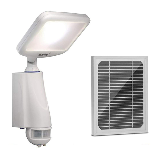
LED Smart Solar Light
IMPORTANT ....
Read this User Manual Before Installing...!!!
Included in this package:
1 – eLEDing Solar Light Body
1 – Wall Mounting Plate w/hardware
Initial Installation
Get Initial test the Battery and LED illuminator before setting up
1. The battery has been pre-charged and connected to the system and ready for use
2. Make sure the main switch is in the OFF position
3. Initially check the LED illuminator and battery by moving the main switch to position ON (SMART), it should light up, then turn the switch
back to OFF for installation. In most cases no pre-charge before using is needed. Switch to OFF for 1-2 days charging under good
sunny day is recommended if it has stored over 12 months.
Mounting the Light Body
1. The light body must only be mounted in a vertical position and it should be mounted at least 6 to 10 feet above the ground
2. Choose a flat and safe mounting surface. Mark the screw positions through the mounting plate screw holes onto the mounting surface
Use 2 or 4 hole mount (Fig. 1-2 & 1-3)
3. For wood, vinyl and metal surfaces mount the back plate directly with provided screws. Drill clearance holes using a 3/16" masonry bit
for surface of concrete, brick or stucco, by insert the anchors provided with screws then position the mounting plate and screw the
fasteners in securely
4. Attach the light body unit to the wall mounting plate by connecting the top hinges. Then secure the light body unit in place by
firmly pushing the light body in toward the mounting base where it locks in position (Fig. 1-3)
5. With the light body firmly secured in it's mounting position, the Pan & Tilt adjustment features can be used to adjust the direction of the
motion detector and the light head for optimal performance and coverage. The direction and angle of the motion detector can
be adjusted (Fig. 1-6). The LED light head can also be adjusted horizontally 180
Mounting and Connecting the Solar Panel
1. The solar panel must be mounted in a non-obstructed position without any shadow on its top where it will receive an average of at least 4
hours daily of direct sunlight all year round. It should be mounted with a tilt of 35°- 80° degrees (Fig 1-8). A sturdy mounting location such
as a wall, roof, on top of patio, under the eaves, secure pole, or floor/ground base. This is required to make sure the solar panel is
fastened down properly for all weather conditions
2. For Northern hemisphere installations the solar panel should be mounted with a Southerly facing position and visa-versa for Southern
hemisphere installation the solar panel should face to the North (Australia, South Africa, South America e. g.)
3. Attach the hardware mounting bracket to the solar panel. Determine what length of the 10' connecting wire cord is needed to reach
the position of the light body and then tie the unused cord behind the solar panel with the plastic zip-tie that is provided (Fig. 1-9)
4. Then mark the screw holes through the mounting bracket and secure the solar panel in position with the provided hardware
5. Firmly plug the solar panel plug into the bottom of the light body. That charging system is actived during a normal sunny, partially sunny or
cloudy day (Fig. 1-5). This unit is chargeable either main switch is OFF or ON (SMART) position, If this does not happen please
check if the plug is fully plugged into the light body or if there is a problem with the wire or solar panel
Yes
Replace or reconnect
the battery
No
1
1
P
Pan & Tilt
T
6
Fig. 1 Installation Steps
Just "One Step" to Begin Using the Light
After the light fixture and solar panel are mounted and connected,
you may immediately begin using the light by just moving the
main switch to the ON (SMART) position. Using the factory pre-
set default profile is recommended (Fig. 2). Note: NO FURTHER
ADJUSTMENTS ARE NECESSARY!!
eLEDing Solar Lights are innovated SMART lights embedded w i t h intelligent
microprocessor control processor. The light has two selectable operating modes,
SMART A MODE (as factory default) and SMART B MODE (Fig. 1-6). Both are
SMART modes of operation and utilize stored energy capacity for the most
optimum lighting efficiency.
The settings for Sensitivity/Range of motion, AUTO Mode or levels of brightness in
dimming control adjustment with ON/SMART B Mode are set, and controlled with
adjustable dials refer by (Fig. 1-4 and Fig. 2)
The family of eLEDing SMART solar lights use an exclusive Intelligent Power
Management (IPM) embedded feature for managing and optimizing the Lithium
based battery for a full range of operation. This optimizes the battery's life cycle to
adapt to most environmental conditions allowing both the battery and light to
perform for many years.
®
Model EE814WX User Manual
1 – Rechargeable Li-Poly Battery 1 – Tempered Glass Solar Panel
2 – Hardware Package with Screws and Anchors
OR
2 Screws
4 Screws
2
T
P
Pan & Tilt
7
Solar Panel Position
, forward and backward 120
o
Push in
3
8
Fig. 2 Light Profiles & Settings
(Fig. 1-7)
o
4
10
9
9
5
Rev. EE814WX 122018 Page 1
Advertisement
Table of Contents

Related Manuals for eLEDing EE814WX


Summary of Contents for eLEDing EE814WX
- Page 1 (Fig. 2). Note: NO FURTHER ADJUSTMENTS ARE NECESSARY!! eLEDing Solar Lights are innovated SMART lights embedded w i t h intelligent microprocessor control processor. The light has two selectable operating modes, SMART A MODE (as factory default) and SMART B MODE (Fig. 1-6). Both are SMART modes of operation and utilize stored energy capacity for the most optimum lighting efficiency.
- Page 2 Acts of God. This warranty does not include liability for incidental or consequential damages. EESGI is not responsible for any damages in excess of the retail purchase price of the product under any circumstances. The consumer is responsible for the installation of, removal of, and reinstallation of the product. Customer Service: 1-(877)579-3889 (M-F, 10am-5pm PST)/info@eesgi.com, www.eleding.com Rev. EE814WX 122018 Page 2...
Need help?
Do you have a question about the EE814WX and is the answer not in the manual?
Questions and answers