
Related Manuals for Plymovent KUA-160/H Series

Summary of Contents for Plymovent KUA-160/H Series
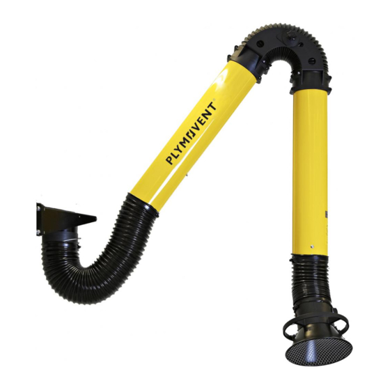
- Page 1 Extraction arm KUA-160/H /S /ATEX Installation and user manual www.plymovent.com...
-
Page 2: Table Of Contents
TABLE OF CONTENTS PREFACE ........................... 2 INTRODUCTION ......................2 PRODUCT DESCRIPTION ..................... 3 SAFETY ........................3 INSTALLATION ......................4 USE ........................... 8 MAINTENANCE ......................9 TROUBLESHOOTING ....................9 SPARE PARTS ......................9 DISPOSAL ........................9 CE DECLARATION ........................10 EN | ORIGINAL INSTRUCTION All rights reserved. -
Page 3: Preface
- type H-D: for hanging mounting, with sealed shut-off valve PREFACE Options and accessories Using this manual This manual is intended to be used as a work of reference for FlowGuard Airflow sensor professional, well trained and authorised users to be able to safely install, use, maintain and repair the product mentioned KUA-160 all types (except for ATEX versions) on the cover of this document. -
Page 4: Product Description
Operation Refer to the available product data sheet for detailed product specifications. The welding fume is extracted through the hood of the arm by a single or central fan. The extraction arm discharges the Ambient and process conditions polluted air to an extraction duct with filter unit or directly to the atmosphere. -
Page 5: Installation
perfect condition in accordance with its intended use and the • Check the working environment. Do not allow unauthorised instructions explained in the user manual. persons to enter the working environment. • Protect the product against water and humidity. Technical specifications •... - Page 6 There are different ways to install the KUA arm. Fig. III on page 11 gives a summary of the relevant paragraphs per arm type (specifically H, ATEX and S) and the preferred mounting sequence. For mounting of the KUA-160/H (hanging; including ATEX): •...
- Page 7 For mounting of the hood: • refer to paragraph 4.6 In case of a KUA-160/H ATEX: subsequently proceed with paragraph 4.7 • 4.4.4 Fan mounting To install an extraction fan on the arm, do the following. Fig. 4.4 • Put the fan on the wall bracket. •...
- Page 8 A (8x) B (8x) For mounting of the wall bracket to the stanchion: For mounting of the hood: • proceed with paragraph 4.4.2 • proceed with paragraph 4.6 • subsequently: proceed with the instructions of Fig. 4.7 (paragraph 4.5.3) Hood Fig.
-
Page 9: Use
180° 180° Fig. 4.10 Connection of the litz wire to the duct Fig. 4.11 • Measure the earth connection between the hood and the duct. The electrical resistance must be lower than 10 ohm. ATTENTION! 180° If the electrical resistance is over 10 ohm, the litz wire connection is not correct. -
Page 10: Maintenance
MAINTENANCE Middle hinge Periodic maintenance The product has been designed to function without problems for a long time with a minimum of maintenance. In order to guarantee this some simple, regular maintenance and cleaning activities are required which are described in this chapter. If you observe the necessary caution Hood hinge and carry out the maintenance at regular intervals, any problems occurring will be detected and corrected before they... -
Page 11: Ce Declaration
CE DECLARATION CE declaration of conformity for machinery We, Plymovent Manufacturing B.V., Koraalstraat 9, 1812 RK Alkmaar, Netherlands, herewith declare, on our own responsibility, that the products: - KUA-2/H ATEX - KUA-3/H ATEX - KUA-4/H ATEX which this declaration refers to, have been manufactured in... - Page 12 ANNEX Fig. I Working reach STANDING MOUNTING KUA-160/S Stanchion Wall bracket Mobile unit 1. Start with par. 4.5.1 par. 4.5.2 par. 4.5.3 2. Hood mounting par. 4.6 par. 4.6 par. 4.6 Fig. IV Mounting examples “H” types KUA-160 + FUA KUA-160 + PA-220 + FUA KUA-160/2 KUA-160/3...
- Page 13 MATERIAL: - The information contained in this drawing is the sole property of 4x M12 lock nut ® PLYMOVENT. Any reproduction in part GENERAL TOLERANCES: - 3RD ANGLE PROJECTION MATERIAL: - The information contained in this or as a whole without written permission drawing is the sole property of of PLYMOVENT is prohibited.
- Page 14 ANNEX Fig. VIII Exploded view 0000101944 0000101537 0000102409 0000102989 0000101907 0000101395 0000101916 0000101903 0000102199 0000102396 0000102398 0000102400 0000102384 0000102387 0000102385 0000102388 0000102386 0000102389 0000101904 0000101905 0000101913 0000101914 0000102397 0000102399 0000102401 0000101912 (2x) 0000102960 0000101906 0000101915 0000101911 0000101908 0000101550 0000114072 0000101937 0000102525 0000101887/010920/B KUA-160...
- Page 15 ANNEX Article no. Description Article no. Description General 0000101916 Antistatic hose L=650 mm/Ø 161 mm, incl. 2 hose clamps 0000101537 Wall mounting bracket, complete 0000102384 Inner frame KUA-160/2H, complete 0000101550 Hood with safety mesh 0000102396 Inner tube KUA-160/2 0000101903 Arm swivel ring KUA-160, incl. rubber collar and washer 0000102397 Outer tube KUA-160/2...
- Page 16 0000101887/010920/B KUA-160 www.plymovent.com...
Need help?
Do you have a question about the KUA-160/H Series and is the answer not in the manual?
Questions and answers