Advertisement
CONTENTS
Section 1 - Introduction ............................................................. Page 1
Section 2 - Installation ............................................................... Page 2
Section 3 - Maintenance ............................................................ Page 4
Section 4 - Troubleshooting ....................................................... Page 9
Section 5 - Installation Drawings................................................. Page 10
Section 6 - Parts/Drawing List ................................................... Page 14
DPU Specifications ................................................................... Page 19
Instrument Specifications ........................................................... Back Page
SECTION 1 - INTRODUCTION
General
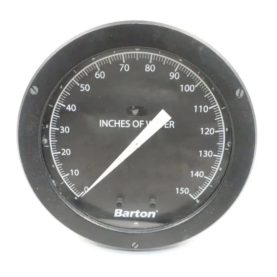
The Model 227C DP Indicator measures liquid flow or liquid level. For flow
measurements, the instrument is connected to the low and high pressure sides
of a primary device (e.g., orifice plate, venturi tube, or flow tube) located in the
process run. For liquid level, the instrument is connected to measure changes in
differential pressure relative to variations of liquid height in a vessel.
Theory of Operation
The bellows within the DPU moves in response to changes in the differential
pressure measured at the primary device installed in the process system.
Movement of the bellows (in direction of decreasing pressure) is mechanically
transferred to the indicator mechanism, which in turn positions the indicating
pointer.
Before installing this instrument, become familiar with the installation instructions
in Section 2. WARNING notes that appear on the following pages of this manual
should be reviewed before proceeding: 3, 6, and 7.
WARNING notes indicate the presence of a hazard which can cause severe
personal injury, death, or substantial property damage if warning is ignored.
DIFFERENTIAL PRESSURE INDICATOR
SAFETY
MODEL 227C
w/224C DPU
Installation Manual
Version 00K25c
ID#10120
11/2000
Advertisement

Summary of Contents for Barton 227C
-
Page 1: Table Of Contents
SECTION 1 - INTRODUCTION General The Model 227C DP Indicator measures liquid flow or liquid level. For flow measurements, the instrument is connected to the low and high pressure sides of a primary device (e.g., orifice plate, venturi tube, or flow tube) located in the process run. -
Page 2: Section 2 - Installation
SECTION 2 - INSTALLATION General The instrument should be inspected at time of unpacking to detect any damage that may have occurred during shipment. Note: The DPU was checked for accuracy at the factory — do not change any of the settings during examina- tion or accuracy will be affected. - Page 3 Mount the DPU on a solid support to minimize vibration. Tighten all points, using a suitable compound; leaks in piping can cause measurement errors. Rotate the housing as necessary to place the connection in the proper position. The DPU has connections in the pressure housings to accommo- date various pipe sizes (refer to Section 5 Outline Dimensional Drawing).
-
Page 4: Section 3 - Maintenance
SECTION 3 - MAINTENANCE Required Tools Tool Purpose Pointer puller Pointer removal Small screwdriver Calibration adjustments Medium screwdriver Bezel removal/DPU bracket screws 1/8" Open-end wrench Calibration adjustments 50 lb. Torque wrench Pressure housing bolts 3/16" Allen socket wrench Pressure housing bolts 5/16"... - Page 5 Calibration Check Normally all that is required to adjust the indicator to the factory-set calibration tolerances is to perform the following calibration check. Connect the instrument to a standard pressure source as shown in Test/ Calibration Equipment, page 4. Remove the plug from the low pressure housing. Apply approximately 150% of the differential pressure range to the high pressure housings.
- Page 6 Set zero and span using the hub for the zero adjustment and the range adjust screw on the movement for span adjustments. Apply 50% differential pressure. If linearity adjustment is required, loosen the drive arm and move the arm to shift the pointer in the direction of the error (approximately 10:1).
- Page 7 If the housing does not move freely — the bellows may be pressurized and is potentially hazardous if further disassembled. Tighten the bolts and return the unit to the factory or authorized Barton service center for repair. Tag the unit and specify “Gas in Bellows”. B. Cleaning/Inspection Procedure...
- Page 8 Perform Pressure Check Procedure under Cleaning and Inspection on page 6. If internal pressure was found, do not continue. Tighten the bolts and return the unit to the factory or authorized Barton service center for repair. Tag the unit and specify “Gas in Bellows”.
-
Page 9: Section 4 - Troubleshooting
SECTION 4 - TROUBLESHOOTING c i f e l l c i f l l i f y t i l l i f y t i e l l d i l t c i o l l o l l i l a b i l c i f... -
Page 10: Section 5 - Installation Drawings
SECTION 5 - INSTALL DRAWINGS... -
Page 14: Section 6 - Parts/Drawing List
SECTION 6 - PARTS DRAWING/LIST 227C Parts Drawing... - Page 15 227C Parts List...
- Page 16 224C DPU Parts Drawing...
- Page 17 224C DPU Parts List...
- Page 18 NOTE: As normally furnished, units having beryllium-copper bellows are fitted with Buna-N O-rings and units having stainless steel bellows, with Viton O-rings. In all cases, however, the O-ring compound must be selected for compatibility with the metered material. Consult factory for other compounds.
-
Page 19: Dpu Specifications
224C DPU Specifications... -
Page 20: Instrument Specifications
Barton Instrument Systems, L.L.C. agrees to repair or furnish a replacement for, but not install, any product which within one (1) year from the date of shipment by Barton Instrument Systems, L.L.C. shall, upon test and examination by Barton Instrument Systems, L.L.C., prove defective within the above warranty.


Need help?
Do you have a question about the 227C and is the answer not in the manual?
Questions and answers