Advertisement
Quick Links
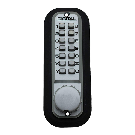
Part #
Part Name
1
Outside Body
2
Inside Body
3
Adjustable Deadbolt
4
Rubber Trim Plate
5
Strike Plate
6
Mortised Striker
7
Spindle (45-55mm)
8
Spindle (35-45mm)
9
Machine Screw M4x50mm
10
Machine Screw M4x35mm
11
Wood Screw M4
12
Non-Combination Tumbler BLUE
13
Combination Tumbler RED
14
Brass Support Pin
15
Tweezers
16
Hex Bolts
INSTALLATION INSTRUCTIONS
Step 1. Change User Code.
If you wish to change your code, see instructions on reverse side.
Step 2. Prep Door for Installation with Template
Note: For pre-prepped 2 1/8" doors, you will only need to drill the top hole.
a. Place supplied template on the door and fold along the door's edge.
b. Mark holes for 2 3/8" or 2 3/4" backset.
c. Drill holes as instructed.
Step 3. Identify Door Handing (Diagram 1 & Diagram 2)
Right-hand doors: From exterior of the door, hinges are on the right side.
Left-hand doors: From exterior of door, hinges are on the left side.
a. The 2210/3210 is factory pre-handed for right-hand doors.
b. To change handing, remove the two blue screws and cover plate from the Outside Body.
c. Move the pin to the hole on the opposite side. Replace plate and screws.
d. If you have a 2210DC/3210DC (Double Combination), the handing pin on the Inside Body
must be placed in the opposite position from the Outside Body.
Step 4. Install Support Pin & Install Hex Bolts (if necessary) (Diagram 3)
a. Install the Brass Support Pin into either hole on the Outside Body as shown.
b. For additional deadbolt support, insert both support pins.
c. If the Hex Bolts did not come pre-screwed into the 2210/3210, screw Hex Bolts into the
top & bottom holes of your lock.
Step 5. Adjust Deadbolt (if necessary) & Install Deadbolt (Diagram 4)
a. The Adjustable Deadbolt is preset to 2 3/8". To adjust, lift pin and slide to 2 3/4".
b. With the arrow on the Adjustable Deadbolt pointed UP, insert the Adjustable Deadbolt
into the door and secure with two Wood Screws.
Step 6. Verify Correct Spindle Length (Diagram 5)
a. With the Adjustable Deadbolt installed, hold the Inside Body and the Rubber Trim Plate
to the interior of the door.
b. Insert Spindle through the Adjustable Deadbolt into the Inside Body as far as possible.
c. The Spindle should extend from the exterior of the door a minimum of 3/8" to a
maximum of 5/8".
d. If the 30-45mm Spindle is too long, cut it to the correct length.
Important: If the spindle extends less than 3/8", it may not engage the lock.
If the spindle extends more than 5/8", it will cause the lock to bind.
Visit LockeyUSA.com for videos & instructions. Still need help? Contact us at 888.395.0163. M-Th 8am - 5pm, Friday 8am - 3pm EST
2210 / 3210 Deadbolt Installation Instructions
Need help? Contact Technical Support at 888.395.0163. M-Th 8am - 5pm, Friday 8am - 3pm EST
2210
3210
2210DC
3210DC
1
1
1
1
1
1
1
1
1
1
1
1
2
2
2
2
1
1
1
1
1
1
1
1
1
1
1
1
1
1
1
1
2
2
2
2
2
2
2
2
4
4
4
4
2
2
4
4
1
1
2
2
2
2
2
2
1
1
1
1
2
2
2
2
Instructions continued on reverse side...
2210, 2210DC, 3210, 3210DC
1
2
7/8
15
16
*2210DC, 3210 & 3210DC
3
4
9
10
11
12
17*
include 2 additional
M4 Machine Screws
Diagram 1
Diagram 3
Diagram 4
Diagram 5
5
6
13
14
Diagram 2
Spindle
Advertisement

Related Manuals for LOCKEY USA 2210

Summary of Contents for LOCKEY USA 2210
- Page 1 For additional deadbolt support, insert both support pins. Diagram 4 c. If the Hex Bolts did not come pre-screwed into the 2210/3210, screw Hex Bolts into the top & bottom holes of your lock. Step 5. Adjust Deadbolt (if necessary) & Install Deadbolt (Diagram 4) a.
- Page 2 INSTALLATION INSTRUCTIONS, CONTINUED Diagram 6 Step 7. Install the 2210/3210 (Diagram 6) (Diagram 7) a. Place the Rubber Trim Plate on the backside of the Outside Body. b. Hold the Outside Body to the door. Hex Bolts should extend into the top and bottom holes. The Support Pin(s) screwed into the...