
Subscribe to Our Youtube Channel
Summary of Contents for Ilsintech SWIFT KF2A
- Page 1 Optical Fiber Arc Fusion Splicer Read this user manual carefully before running KF2A SWIFT KF2A USER MANUAL WWW.ILSINTECH.COM...
- Page 2 A Class Device Users need to understand that this device(A Class) has (Broadcasting and obtained EMI(Electromagnetic compatibility) and been communication device, commercial designed to be used in places other than home. use) Telephone 042 671 5607~8 Homepage www.ilsintech.com E-mail saleskorea ilsintech.com...
-
Page 3: Table Of Contents
Contents I. SAFETY INSTRUCTION II. PRODUCT SPECIFICATIONS AND COMPONENT 2.1 Product specifications 2.2 Product package III. PRODUCT OUTLINE 3.1 Function buttons 3.2 Component name IV. INSTRUCTIONS FOR USE 4.1 Power supply 4.2 How to turn the power ON/OFF 4.3 Fiber cleaning 4.4 Inserting fiber to protecting sleeve 4.5 Fiber stripping 4.6 Fiber cleaning... - Page 4 6.3 Stripper Mode 6.4 Optional Splice Function 6.5 Splice Result Saving VII. SUB MENU 7.1 Language 7.2 Power Saving Function 7.3 Menu Lock 7.4 Other Option VIII. AUXILIARY MENU 8.1 Calibration of Arc-discharge 8.2 Electrode IX. MENU MANAGEMENT 9.1 Pop-up Menu Setting 9.2 Setting Automatic Heater 9.3 Setting or Cancelling Error X.
- Page 5 12.3 Motor Operation 12.4 LED Test 12.5 Maintenance Information XIII. PROBLEM OCCURRENCE AND QUESTION 13.1 Power Supply 13.2 Splice 13.3 Tube Heater Operation 13.4 Management 13.5 Other Settings XIV. PC PROGRAM INSTALLATION 14.1 Installation Procedure XV. WARRANTY AND REPAIR 15.1 Warranty Period and Limit of Responsibility 15.2 Before sending the equipment 15.3 For more effective maintenance and repair of the equipment, 15.4 Transport of the equipment...
-
Page 6: Safety Instruction
Safety instruction Swift KF2A is designed to be used conveniently on both indoor and outdoor work sites. Its use is easy and simple but make sure to read this instructions prior to prevent accidents and malfunctions before using Swift KF2A. This user guide provides information necessary for safe operation. - Page 7 Refer to the following when using the battery. When an improper battery which is not provided by Ilsintech is used, it may incur smoke, damage of equipment, burn, injury or even death. Do not dispose the battery into fire.
- Page 8 Wear safety goggles when working on splicing. It is very dangerous if a piece of fiber chips get in skin or eye. Do not use Swift KF2A around high temperature or flame. It may incur injury or equipment damage. Caution for high temperature...
- Page 9 Swift KF2A should be accurately adjusted and treated in alignment. Do not give it a strong shock, either. Use a carry case to carry or to keep Swift KF2A. The carry case keeps the equipment from humidity, vibration and shock during storage and transportation and prevents possible damage to KF2A.
-
Page 10: Product Specifications And Component
Product specifications and component 2.1 Product specifications Item Description Fiber alignment Fixed V-Groove (Clad to Clad Alignment) Applicable fibers 0.25mm, 0.9mm, 2.0mm, 3.0mm Indoor cable Number of fiber core Single applicable Fiber diameter Clad diameter: 125 ㎛, Coating diameter: 150 ㎛~3mm Cleaved length 5.0mm~16mm Splice mode... -
Page 11: Product Package
3,000 splices Terminals USB, RCA, external power(DC 12V vehicle cigar jack splice) 2.2 Product package 2.2.1 Standard package Item Model name Quantity Fusion splicer Swift KF2A AC adapter Spare Electrodes EI-19 1 set Battery KF-3400 Cooling tray CT-01(40mm) Fiver Holder... - Page 12 KF-LC, KF-ST, KF-L900 (Choose one) Sleeve S09-C, S09, S30-C, S30 Sleeve clamp SC-01 Work belt WB-01 SOC connector SC, LC, FC, ST [See Ilsintech website.] Carrying case Hard Case Manual Stripper CF-02 External Power DC 12V Available for car cigar jack...
-
Page 13: Product Outline
Product outline 3.1 Function buttons Button Description Press and hold about 1 second to turn the power ON/OFF. Press and hold about 1 second when power is on and splicer turns off. Move the cursor to the left. Move fiber on manual mode and adjusts camera’s focus. It loads stripping popup menu. -
Page 14: Component Name
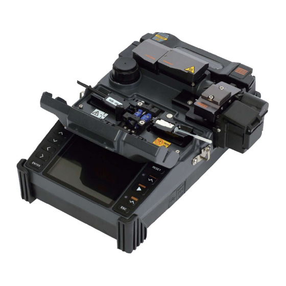
3.2 Component name Sleeve heater Stripper Wind cover Cleaver Monitor Battery... - Page 15 DC OUT Heater Heater cover...
-
Page 16: Instructions For Use
Instructions for use The following is the initial screen of Swift KF2A. For accurate splice result, splice mode, stripping mode and heater mode should be properly selected. Basic information on Swift KF2A is displayed on the initial screen. Check whether the proper mode is selected before splice. -
Page 17: Power Supply
4.1 Power supply Battery pack is built in at the battery chamber. Loosen the bolts at the bottom cover and exchange battery. Please be cautious when you detach the battery from the chamber. 4.1.1 Built in battery... - Page 18 4.1.2 Battery charging Make sure you check the voltage, frequency and then the DC cable of AC/DC adaptor connects to the DC jack of the battery before charging the battery When the battery is fully charged, LED will turn green and power is disconnected, activating protection circuit to avoid overcharge.
-
Page 19: How To Turn The Power On/Off
4.2 How to turn the power ON/OFF To turn on the power of Swift KF2A, press and hold about 1 second with the wind cover closed. After the entire functions including motors are initialized, the initial screen is subsequently displayed as follows. For accurate splice, splice mode and heater mode should be properly selected. -
Page 20: Fiber Cleaning
Fiber cleaning Wipe fiber clean with soft cloth or cotton moistened with alcohol. Fine dust on the surface of the fiber may increase loss after splice and incur damage on the fiber after heating. Inserting fiber to protecting sleeve Put fiber into the protective sleeve. -
Page 21: Fiber Stripping
4.5 Fiber stripping Automatic stripper of KF2A automatically performs accurate stripping with single fiber. This thermal stripper does not incur cracks on stripped fiber with superb tensile force. Stripping length of the fiber can be up to 28.0mm. To keep the equipment’s optimal performance, thoroughly understanding and memorizing the instructions is extremely important for proper use. - Page 22 Use ethyl alcohol with a purity level of 96% or higher. Heater warms up. Make preparations by opening up the heater cover and slide cover. Install fiber to be stripped on the holder as in the figure. The minimum stripping length is 18mm. iii.
- Page 23 4.5.1 Maintenance (1) Blade replacement and adjustment Remove the blade by unscrewing the bolt as shown in the figure when its fails stripping. Removal should be done after moving the slider and it stays to the left position. Assemble a new blade in reverse order of the disassembly process. (composed as 1 pair of each piece both at the top and the bottom) Setting and stripping can be done properly with no on the both top and bottom.
-
Page 24: Fiber Cleaning
4.6 Fiber cleaning The alcohol dispenser of KF2A releases a fixed cleaning agent for fiber cleaning. Be careful not to soak this equipment in any amount of liquid Keep it clean at all times as it is vulnerable to humidity and dust. Keep and use it at room temperature as it can become deformed due to high temperature. -
Page 25: Fiber Cleaving
4.7 Fiber cleaving The automatic cleaver of KF2A cleaves by 90 degree angle cleaving with a single fiber. Stripping should be in a proper condition. Fiber alignment in the holder must be in an appropriate condition. The blade condition and height of the blade at the cleaver should be maintained in a proper manner. - Page 26 iii. Check the cleaved the end face of the fiber with the cover open. <Φ250 type> <Connector type> Remove the cleaved fiber and holder. Be careful not to leave any dust or foreign substance on the fiber. Cleaved chips are collected by an automatic chip collector. For the detailed use of cleaver, refer to the instructions for blade use.
- Page 27 4.7.2 How to change blade channel (cleaving locations) Remove the cleaver from KF2A main body using a hex wrench as in the figure. Then remove the chip box using a hex wrench as in the figure below. iii. Open the cover; with the slider advanced, then unscrew the set screw using a wrench as in the figure.
- Page 28 Turn the blade counterclockwise by 1 mark with a cotton swab. Assembly is done in reverse order. 4.7.3 Blade replacement With cleaver removed from KF2A, unscrew the set screw using a wrench as in the figure. Insert a wrench from the bottom of the cleaver as in the figure and properly unscrew the set screw from the slider.
- Page 29 iii. Turn the wrench bolt; put it in Cam Pin and then remove it from the slider by pulling with a tweezers, etc. Pay special attention in order to prevent blade damage while replacing it. Assembly is done in reverse order of disassemble and the set screw should be firmly tightened.
-
Page 30: Sleeve-Heater
When the blade is adjusted to the proper height, tighten the set screw of slide. The height adjustment of the blade is closely related to cleaving quality . 4.8 Sleeve-Heater The sleeve heater of KF2A reinforces spliced point of the single fiber. The quality of fusion splicing on the fiber should be good. - Page 31 iii. After settling the fiber, turn on the heater by pressing . (Heating time 20sec) Remove the sleeve protected fiber by opening the cover when the cooling is completed. The better positioning of the fibers will shorten heating time...
-
Page 32: Splice Procedure
4.9 Splice procedure The status and cleaved quality of the fiber can be monitored by using an image processing system by Swift KF2A. For better splice result, however, visual inspection is required also. In auto mode, the splice procedure begins automatically as the wind cover is closed. -
Page 33: Removing The Spliced Fiber
Hold the fiber on the left and open the clamp on the left. Open the fiber clamp on the right. Hold both sides of spliced fiber and separate the fiber from Swift KF2A with care. 4.11 Heating protection sleeve Move spliced point to the center of the protecting sleeve. -
Page 34: Use Of Work Belt
4.12 Use of Work Belt The work belt of Swift KF2A is a type of auxiliary equipment that combines with its main body to facilitate working at a manhole, utility pole, etc. 4.12.1 Use of Work Belt Work belt components... -
Page 35: Maintenance Of Splice Quality
Maintenance of splice quality 5.1 Cleaning and Inspection before splice 5.1.1 V-Groove cleaning When the inside of V-Groove is contaminated, splice quality may deteriorate. Thus, it is important to regularly inspect and frequently clean the V-Groove as follows. Open the wind cover. ii. - Page 36 5.1.2 Pusher Block cleaning Pusher Block contamination incurs poor splice quality due to irregular pressure apply to the fibers Thus, it is important to frequently inspect and regularly clean it. 5.1.3 Cleaning Prism Contamination of the prism creates inaccurate monitoring about the fiber cladding location, which causes high loss rate.
- Page 37 5.1.4 Cleaver cleaning If the cleaver’s blade and rubber pads are contaminated, the cleaving quality may deteriorate. In turn, the splice loss rate can be consequently increased. Thus, clean the cleaver blade and rubber pad frequently using a cotton swab moisten by alcohol. This is critical to keep the cleaved quality of the fiber.
-
Page 38: Regular Inspection And Cleaning
5.2 Regular inspection and cleaning To ensure splicing quality, regular inspection and cleaning is required. 5.2.1 Object lens cleaning Contamination on object lens’ surface disturbs the identification of fiber core location and consequently incurs high splice loss. Thus, 2 object lenses should be kept clean at all times. - Page 39 5.2.2 Electrodes replacement It is recommended to replace the electrodes after using appx 3,000 times. If the number of arc exceeds the replacing cycle, a message for electrodes replacement is displayed on the screen. Without electrodes replaced splice loss increases and the tensile force at the splicing point weakens.
-
Page 40: Menu
Menu 6.1 Splice Mode The optimized settings for an accurate optical fiber splicing are composed of following splice elements which rely on the combination of fibers and differences of each fiber. Elements to adjust discharge and heating Elements to calculate estimated loss ... - Page 41 OM2-OM4 Splice mode for OM2 to OM4 multimode fibered connector. Other splice modes not shown above are stored at database MISC in the splicer. New splice modes are updated as available. Please contact Ilsintech for the new splice mode available..
- Page 42 Selection of a splice mode Select an appropriate splice based on the type of the optical fiber to be spliced. Ready ① Press ENTER key on the initial screen to open Initial Screen menu When splice mode is selected, available splice modes are displayed.
- Page 43 Generation or removal of a splice mode [Generation of a splice mode] Select BLANK in [SELECT SPLICE MODE] Initially 14 splice modes are saved in the unit and other modes are presented as a blank. SELECT SPLICE MODE Select a blank splice mode, press right direction arrow and then, push ENTER key.
- Page 44 Edit of reference or splice mode Splice elements composing each splice mode can be modified. Amount and time of discharge, which are the most important two factors, can be modified by following way. ① Move the cursor to modify a splice mode in Selection of splice mode edit splice mode edit menu.
- Page 45 Parameters for 14 basic splice modes.. The limited number of parameters are displayed on the screen for simple operation. The additional parameters not shown hereunder are configured to optimum at the factory. Parameter Description Displays splice mode store at the database. Selected mode from Fiber types the modes in the database is to be copied to splice mode at user program area.
- Page 46 Splice mode edit Splice mode edit is used for user to configure many splice modes to make the best result out of the splicing environment. The following describes utilizing a variety of parameters and the function. Parameter Description Displays splice modes stored in database, allowing to select Fiber type proper mode.
- Page 47 Configures fiber location at the center to splice. In case the MFD of left/right fiber, you may adjust center location Center Location to improve splice quality. Configures initial arc amount before the fiber advances to align. If the initial arc amount is low, this will result in offset taking place Initial Arc due to bad end face angle.
- Page 48 Configures re-arcing time.. In Splice Mode Edit, this allows re-arcing amount and Arc Vol2 at Re-Arc Time the same arc amount automatically. When Arc2 is set as “ON” and “OFF”, re-arcing is automatically set at “ON” and “OFF” Sometimes, the splice loss rate increases when the fiber Pulling splice becomes thinner.
- Page 49 [Mode Title Insert / Footnotes / Password] Character list is displayed when selecting Mode Title / Footnote / Password ① Select necessary letters using and press ENTER key to confirm the selection. ② Once character input is completed, move the cursor the [FINISH] and press Enter key.
-
Page 50: Heater Mode
6.2 Heater Mode A Heater has 11 modes. The most suitable heater mode needs to be selected before using a protection sleeve. For different sleeve tubes, an operator could utilize the best mode. The reference of this mode can be found in database. The user can put a mode into the user’s program after editing and copying or can edit in user program mode. - Page 51 Create and delete heater modes. Creating and deleting heater mode is same as doing splice mode. Heater mode modification The heater mode menu saved in heater mode can be changed. ① Select Edit mode in [Heater Mode Selection] [Heater mode menu selection] menu using the cursor.
- Page 52 [Outline of heater mode] Set value Description Others 60mm Standard 60mm micro sleeve 40mm Standard 40mm micro sleeve 45mm sleeve for 0.9mm cable S09-C 22mm sleeve for SOC(SC-0.9mm) 45mm sleeve for2.0mm cable 45mm sleeve for3.0mm cable S30-C 32mm sleeve for SOC(SC-3.0mm) LC09/20-C 25mm sleeve for SOC(LC-0.9 , 2.0mm) ST09-C...
- Page 53 Variables Description Sleeve type selection Sleeve type All the contents in heater mode list are displayed. Users can either copy program mode or select from the list. Method name Describes the heater mode in the [Sleeve Type] screen. ...
-
Page 54: Stripper Mode
6.3 Stripper Mode There are 7 stripper modes. Since the types of fibers are varied, select the most suitable stripper mode should be selected. Stripper mode selection Stripper mode selection ① [Select Stripper Mode] is selected in [Main Menu] to display stripper modes. Stripper mode selection ②... - Page 55 Create and delete stripper mode Creating and deleting heater mode is same as doing splice mode Edit Stripper Mode The stripper settings saved in stripper mode can be changed. ① Select edit mode within [Stripper mode [Stripper mode selection] selection] menu using cursor.
-
Page 56: Optional Splice Function
6.4 Optional Splice Function Allows setting general parameters of every mode for splicing and tube heater operation. Splice option ① Select [Splice Option] in main menu to display menu list for splice on the screen. Splice setting ② Users are allowed changing some of the parameters. - Page 57 Menu Configuration Parameters Decscription General When you configure Auto Execution to “ON”, this will enable Auto Execution automatic splice process. As you place the fiber to the splicer and close dust cover, splice process will start automatically. When you configure Temp. Pause to :ON”, the splicer will stop right after the fiber alignment.
- Page 58 Arc Compensation When you configure Pressure to “ON”, this will compensate automatically Pressure the difference in air pressure. Applies arc compensation value by the temperature. The user can’t Temperature inactivate the function. Condition of Fiber Distance Adjust the distance between two fibers. adjustment The user can’t inactive the function.
-
Page 59: Splice Result Saving
6.5 Splice Result Saving This equipment has memory space in which 2000 splice results can be saved. Splice result display Splice results saved in the memory can be displayed, added and edited. Saved data can be downloaded to PC. Splice result saving ①... - Page 60 Deleting splice result A part of or an entire splice result saved in the memory can be deleted. ① Select [Clear Memory] in [Splice Memory] to display menu for deleting splice results. [Clearing entire splice results] ② Move to [Clear All Data] and press ENTER key. Yes or No selection appears. ③...
- Page 61 Select [Splice Memory]...
-
Page 62: Sub Menu
Sub menu This menu is composed of a set of sub menu, each of which controls detailed function of the equipment. ① Press ENTER key and cursor to move sub- menu. ② Each setting can be selected and modified. 7.1 Language Language change ①... -
Page 63: Power Saving Function
7.2 Power Saving Function Power saving function is essential for energy preservation. When the battery is used without setting of power saving function, the number of connections decreases so it is recommended to use power saving function. Setting power saving function ①... -
Page 64: Menu Lock
7.3 Menu Lock ① Select Menu Lock in [Sub Menu] and press ENTER Key. ② Select password and press ENTER key. Create a password by moving the cursor and press finish key to set or cancel the menu lock. If you select password locked, following items cannot be modified. - Page 65 ① Select Splice Mode and press ENTER key. Then you will be able to set or cancel menu lock in the menu appeared. If you choose Yes, whenever you are trying to modify parameters or settings of splice mode, “Password Locked”...
- Page 66 ① If you choose Splice Memory and Yes, deleting splice results cannot be made. Even if password locked is set to Yes, unless the lock of each mode is set Yes, modification of each mode is not locked.
-
Page 67: Other Option
7.4 Other Option In other option in sub menu, additional functions can be set. ① Password change and buzzer sound change, theme change can be made in System Setting. Do not forget the password you’ve created, if you forget it, the equipment should be sent to the factory to initialize the password. - Page 68 ② Program version shows the current version of operation program. ③ Anglelimit on Arc-discharge calibration, you can set limitations on angle upon calibration of discharged amount.
-
Page 69: Auxiliary Menu
Auxiliary menu 8.1 Calibration of Arc-discharge Arc-discharge current needs to be calibrated in accordance with the changes in temperature, humidity and air pressure of surrounding area. Temperature, humidity and air pressure sensors are useful in calibrating arc-discharge depending on external conditions. - Page 70 ③ Press ENTER key Arc-discharge is carried out after aligning the fiber. The arc-discharge current can be adjusted in accordance with arc-discharge status. Initial cleave angle is not related to the parameter “cleave loss” in splice mode. The initial cleave angle can be set independently for the purpose of controlling arc-discharge current.
-
Page 71: Electrode
8.2 Electrode 8.2.1 Electrode Stabilization Sometimes, splice loss rate grows due to unstable arc-discharge current caused by surrounding environmental factors. Users need to understand that it takes quite a time for the arc fusion splicer to generate stabilized arc-discharge when it is used in high or low position. - Page 72 8.2.2 Electrode Replacement The equipment needs to be cleaned in a regular manner as electrodes are being worn off and silica oxide particles are deposited continuously. It is recommended to set the replacement period to 3,000 times of discharge. When the discharge count exceeds 3,000 times, a message to request for the replacement of electrodes appears.
- Page 73 (i) Correctly place an electrode into the V-groove of electrode base. (ii) Fix electrode cover by tightening screws. Be careful not to damage the electrodes while replacing them. Turn the handle while pressing electrode cover at a correct position. ⑤...
- Page 74 8.2.3 Electrode Caution User can check the replacement timing through Electrode Menu 8.2.4 Electrode Used User can check the current usage count through Electrode Menu...
- Page 75 Clearing Arc-discharge Count Users can clear the record of arc-discharge count. ① Select [Clear Arc Count]. ② Select Yes and press ENTER key to delete the record. This is a function required to be done after replacing electrodes.
- Page 76 Date and Time Setting Users can set the date and time when data is saved in the equipment. ① Select [Calendar]. ② The current date and time are displayed. Sensor Value Various sensors are used in the equipment to display current temperature, air pressure and battery voltage.
-
Page 77: Menu Management
Menu Management 9.1 Pop-up Menu Setting Splice mode and heater mode, which are frequently used, can be registered as a pop- up menu so that mode change to those functions can be done promptly by pressing up or down key. Press ... -
Page 78: Setting Automatic Heater
② Heater mode registration Press ENTER Key → Select Heater Mode → Press Key → Pop-up menu registration box appears → select necessary number using up and down keys → Press ENTER Key → Registration completed 9.2 Setting Automatic Heater It is a convenient function when continuously splice works have to be carried out. -
Page 79: Error Message
Error Message 10.1 FIBER DIRTY An error message that indicates that there are foreign substances on the prepared optical fibers more than normal limit. Clean the fibers and set again. 10.2 ALIGNMENT ERROR An error message appears when the fibers are not placed in the middle of electrodes and V-groove or object lenses or prism is stained. -
Page 80: Fiber Too Long
Conduct LED examination, if there is an error, contact ILSINTECH Co., Ltd. 10.4 FIBER OVER ANGLE It appears when the measured value of fiber cleave angle is bigger than angle limit. Check the condition of fiber cleaver and reset the ... -
Page 81: Fiber Thin
10.6 FIBER THIN It appears when the spliced part is thinner than reference value after conducting splice. Reduce the length to pull in the pulling splice menu. Check whether arc-discharge is too strong or discharge time is too long. ... -
Page 82: Splicing Problem Solving
Splicing problem solving 11.1 When loss is high Any dust or foreign substance on the fiber surface may incur poor splice. Clean the fiber surface sufficiently. Do not clean the fiber after cleaving to prevent dust from being ... -
Page 83: Abnormal Splicing Operation
Open the wind cover again and then close. If discontinues, open the wind cover, press and then turn off the power. Then contact Ilsintech. The error message “Too Long Fiber” is continuously generated. Turn off the power and contact Ilsintech. ... -
Page 84: Other Menu
Other Menu Self-Diagnosis Test 12.1 The operational status of the functions of SWIFT KF2A can be tested by a simple self- diagnosis test. Procedure ① Place a fiber into the SWIFT KF2A and select [Self Diagnosis] in the menu. Check following matters... -
Page 85: Dust Test
Conduct [Dust Test] again. Refer to “Splice quality maintenance” page for the way to clean them. ④ Press Esc key to stop dust test. If the user cannot remove dust on the wind cover prism or lenses after cleaning them, contact ILSINTECH Co., Ltd. -
Page 86: Motor Operation
① Select [Led Test] in [Other] ② Remove any fibers placed in the splicer and press ENTER key to start the test. ③ After test, if “ERROR” message appears, contact ILSINTECH Co., Ltd. ④ Press “Esc” to end dust test. -
Page 87: Maintenance Information
Maintenance Information 12.5 When [Maintenance Information] is selected, below information appears. Parameter Description Shows the year, month and date when the equipment Production Date was produced. The number of discharges done after replacing Arc-discharge Count electrodes. It can be initialized to ‘0’ by executing [Clear Arc Count]. Total Arc-discharge Shows the total arc-discharge count of the equipment. -
Page 88: Problem Occurrence And Question
Another case is that the battery pack is damaged or its service life has been over. If LED is still blinking when charging a new battery pack, contact ILSINTECH Co., Ltd. ④ LED of charger is not turned on. -
Page 89: Splice
If the fiber is bent or twisted, place the bent part upward. Cleave angle, arc-discharge conditions and cleanness of fiber affect the loss rate. If the loss rate still is high after conducting above measures, contact ILSINTECH Co., Ltd. An annual maintenance and repair are required for marinating good splice quality. -
Page 90: Tube Heater Operation
Turn on the equipment and check power saving settings. ⑥ How to change the error limit values of cleave angle, splice loss and fiber angle? Refer to [Splice Mode Edit]. ⑦ Error message can be ignored. Refer to [Splice Other Option]. ⑧... -
Page 91: Management
Press Heat key times to cancel heating. It cannot be cancelled by pressing Reset key. 13.4 Management ① How to prevent modifying function list? Refer to [Menu Lock]. Howe to lock the “Splice”, “Edit” or “heater mode”? ② Refer to [Menu Lock]. ③ Password is lost. Contact ILSINTECH Co., Ltd. -
Page 92: Other Settings
13.5 Other Settings ① [Arc-discharge calibration] is repeated many times until “Test Completion” is displayed. More calibration is required when surrounding environment is radically changed or after electrodes are replaced. ② “Test Completion” is not displayed even though the calibration has been repeated many times. -
Page 93: Pc Program Installation
PC Program Installation 14.1 Installation Procedure ① Move the provided driver onto PC and save it. ② Connect the equipment to PC with a USB cable. ③ New hardware is found and USB Serial Port Driver is installed. ④ Hardware update wizard is activated. Select “Yes, now and every time…”... - Page 94 ⑥ Select “Search for the best…” and “Include this location…”as shown below and click Browse to find the location when FTDRIVER is saved. ⑦ When clicked Next below screen appears. ⑧ Click Finish .
- Page 95 ⑨ When the installation of USB Serial Converter Driver is completed, Hardware update wizard is activated again. ⑩ Select “Search for the best…” and “Include this location…”as shown below and click Browse to find the location when FTDRIVER is saved. ⑪...
- Page 96 ⑫ Click Finish to complete the installation of USB Serial Port. ⑬ Select My PC and click mouse right button and select Properties. ⑭ Select [Hardware] tap and click [Device Manager].
- Page 97 ⑮ Click [Fort (COM & LPT)] and select “USB Serial Port”. ⑯ In the “USB Serial Port Properties” window, set the speed of Bits per second to 115200. ⑰ In “Advanced Setting for COMx” window, click “COM Port Number” and select the port to be used in COM3 ~ COM10 Port.
- Page 98 <Splice Results> window in chronological order. Detailed data can be shown in <Detail Display> window when an item is clicked. Splice results are recorded as KF2A.txt in the folder where SWIFT KF2A Splicer program is installed or on the desktop.
-
Page 99: Warranty And Repair
② application of abnormal high frequency voltage, ③ negligent handling, ④ handling or maintenance not meeting the operational procedures or instructions presented in service manual and ⑤ seal sign being already damaged. 15.2 Before sending the equipment Please contact ILSINTECH Co., Ltd first. -
Page 100: For More Effective Maintenance And Repair Of The Equipment
15.3 For more effective maintenance and repair of the equipment, ① buyers should include a note which contains (Name, department, company, address, telephone no, Fax no, e-mail address) ② arc fusion splicer’s serial no and ③ error messages appeared when an incident or breakage occurred. Possibly with a brief explanation of the symptoms or reasons for repair including the condition and time of incident, current condition and monitor condition, etc. - Page 101 Product Warranty Product name SWIFT KF2A Manufacture no. Date of purchase Name TELEPHONE Customer Address Warranty 1. This product is manufactured through strict quality management and inspection. over defective parts This product guaranteed for one year from its date of purchase.
Need help?
Do you have a question about the SWIFT KF2A and is the answer not in the manual?
Questions and answers