Table of Contents
Advertisement
Quick Links
Sound Detector Hookup Guide
Introduction
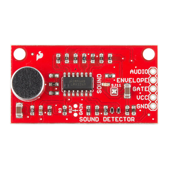
The Sound Detector is a small board that combines a microphone and some processing circuitry. It provides not
only an audio output, but also a binary indication of the presence of sound, and an analog representation of it's
amplitude.
SparkFun Sound Detector
SEN-12642
Advertisement
Table of Contents

Related Manuals for sparkfun SEN-12642

Summary of Contents for sparkfun SEN-12642
- Page 1 The Sound Detector is a small board that combines a microphone and some processing circuitry. It provides not only an audio output, but also a binary indication of the presence of sound, and an analog representation of it’s amplitude. SparkFun Sound Detector SEN-12642...
-
Page 2: Quick Start
SparkFun Sound Detector (with Headers) SEN-14262 Covered in This Tutorial This tutorial will guide you through hooking up and using the Sound Detector. It will examine how the circuit works, explain some details about getting the best performance from the Sound Detector, then present two different projects that demonstrate how to use it. - Page 3 With it’s 3 outputs, the board itself is a lot more flexible. To explore that flexibility, read on. Looking Closer Three Outputs? The Sound Detector has 3 separate outputs. It’s easiest to see what each is doing with a graph. The following illustrates how the sound detector responds to a series of sound pulses.
-
Page 4: First Stage
Finally, the red line is the gate output. This output is low when conditions are quiet and goes high when sound is detected. How It Works Having examined the outputs, lets also take a quick walk through the schematic, to gain an understanding of how each stage works. - Page 5 if(Vin > 0) Vout = 0; else Vout = Vin * -2.2 The opamp inverts and amplifies the signal. When it’s output swings high, D2 turns on, and charges C1. When the opamp output is high or not swinging, D2 is turned off, and C1 discharges through R9. Thus, C1 tracks the peaks of the input signal.
-
Page 6: Power Supply
sensitive to loading, it’s internally buffered with a JFET (junction field-effect transistor). Due to the mechanical and electronic tolerances involved, some capsules are more sensitive than others. Also, the JFET is rather sensitive to noise on the power supply. Both of these factors need to be accounted for when deploying the Sound Detector. -
Page 7: Lights Out
It’s most likely that you’ll find the detector to be too sensitive. In testing the board for this writeup, noisy air conditioning and music in the next office were enough to set it off. To make the board less sensitive, you can lower the preamplifier gain by populating R17 in parallel with R3. -
Page 8: Software Example
SparkFun Wish List RedBoard - Programmed with Arduino DEV-11575 At SparkFun we use many Arduinos and we're always looking for the simplest, most stable one. Each board is a bit… Break Away Male Headers - Right Angle PRT-00553 A row of right angle male headers - break to fit. 40 pins that can be cut to any size. Used with custom PCBs or gen…... - Page 9 * Using Arduino IDe 1.0.5 * Tested on Redboard, 3.3v/8MHz and 5v/16MHz ProMini hardware. * This code is beerware; if you see me (or any other SparkFun employee) at the * local, and you've found our code helpful, please buy us a round! * Distributed as-is;...
- Page 10 // is called. // It queries the state of that pin, and sets the onboard LED to reflect that // pin's state. void soundISR() int pin_val; pin_val = digitalRead(PIN_GATE_IN); digitalWrite(PIN_LED_OUT, pin_val); void setup() Serial.begin(9600); Configure LED pin as output pinMode(PIN_LED_OUT, OUTPUT); // configure input to interrupt pinMode(PIN_GATE_IN, INPUT);...
- Page 11 Materials Again, we start with the Sound Detector, then add the following parts. Sound Detector Analog Example SparkFun Wish List Dot/Bar Display Driver - LM3916 (VU Taper) COM-12695 This is the LM3916 Dot/Bar display analog-controlled LED driver that uses a more logarithmic/VU scale, which mak…...
- Page 12 Which translates thusly onto a solderless breadboard. The assembled, operational version looks like this. Listening to “The Lonely Bull” by the Ventures Sound picked up by the microphone is now translated onto the bar graph. The louder the sound is, the more LEDs light up! A few of notes about the circuit.
-
Page 13: Troubleshooting
2 of this tutorial), though you’ll have to modify the file path to analyze a wav file if your own. Finally, the Sound Detector has been added to the sensors category in the Sparkfun Fritzing Library. See Also...
Need help?
Do you have a question about the SEN-12642 and is the answer not in the manual?
Questions and answers