Table of Contents
Advertisement
Quick Links
Advertisement
Table of Contents

Related Manuals for SystemAir SRC


Summary of Contents for SystemAir SRC
- Page 1 Installation and user manual Smart Remote Control...
- Page 3 INSTALLATION INSTRUCTION English NOTICE D’INSTALLATION Français INSTALLATIONSHANDBUCH Deutsch ISTRUZIONI INSTALLAZIONE Italiano INSTRUCCIONES DE INSTALACIÓN Español...
-
Page 4: Table Of Contents
2.4.3. FAN CONVECTOR UNIT ................................................4 2.4.4. HEAT PUMP ON WATER CIRCUIT ..............................................4 3. DIMENSIONS AND INSTALLATION ..............................5 3.1. POWER AND COMMUNICATION UNIT ......................................5 3.2. SRC REMOTE CONTROL ..........................................6 3.3. WIRING................................................7 3.3.1. NETWORK PRINCIPLE .................................................7 4. INITIAL SETTINGS ..................................... 8 4.1. -
Page 5: General Recommendations
POWER SUPPLY MUST BE SWITCHED OFF BEFORE STARTING WORK IN THE ELECTRIC CONTROL BOX 1. GENERAL RECOMMENDATIONS Please read the following safety precautions very carefully before installing the unit. 1.1. SAFETY DIRECTIONS Follow the safety rules in forces when you are working on your appliance. The installation, commissioning, use and maintenance of these units should be performed by qualified personnel having a good knowledge of standards and local regulations, as well as experience of this type of equipment. -
Page 6: Presentation
4 SRC 2. PRESENTATION 2.1. INTRODUCTION HMI (Smart Remote Control) is a control interface for control systems. It has the advantage of being a remote control system. The control can be centralized and is done either individually or by zone (unit group). -
Page 7: Dimensions And Installation
3. DIMENSIONS AND INSTALLATION 3.1. POWER AND COMMUNICATION UNIT The power and communication unit contains: a 220 V ~/24 V DC transformer ² a Modbus RTU protocol protection card ² Ø5 To install the power and communication unit: Mount 2 screws on the wall, respecting the dimensions. -
Page 8: Src Remote Control
6 SRC 3.2. SRC REMOTE CONTROL is designed to be mounted on a wall. There are two mounting options: Method 1 To install the SRC: Mount 2 screws on the wall, respecting the dimensions. Connect the RJ10 cable Attach the remote control to the screws. -
Page 9: Wiring
(26 to 22 AWG). Each network is limited to 31 units and a distance of 1,000 meters. However, we recommend using a repeater well before reaching the limits and in accordance with the geographical constraints. SRC communication board A+B- A+B-... -
Page 10: Initial Settings
None Chiller B, Address 2 Cancel HMI termination HMI termination Display settings Display settings Display settings Caution In the case of heat pump management on water circuits, the SRC’s clock must be synchronized with that of one of the units. -
Page 11: Display Setting
4.2. DISPLAY SETTING System preferences Unit language English Unit date and time 05.02.2020 13:35:20 This menu allows you to manage the screen brightness when it is active or in standby mode. It is also possible to set the standby time. Use 24 hours time format Example 13.00 Clock sync. -
Page 12: Configuration Of The Control Type
Configuration dip switch (SYSLOGIC control) AC motor (TCONTROLPOD control) EC motor (TCONTROLPOD control) zone creation Information To make it easier to identify the fields when using the SRC, it is possible to name each of the zones. -
Page 13: Addressing In Mini-Bms Mode
5.1.1. ADDRESSING IN MINI-BMS MODE Caution Before setting up the SRC, it is important that all slave units are addressed. Maximum of 31 units ² Addresses between 1 and 31 ² Settings Devices Devices Devices Address 1 Address 1 Configure addresses... -
Page 14: Fan Convector Unit Configuration
12 SRC 5.1.3. FAN CONVECTOR UNIT CONFIGURATION must be set up according to the configuration of the fan convector units. 5.1.3.1. FAN CONVECTOR UNIT A Type A fan coils are equipped with SYSLOGIC control. This electronic card has a DIP switch to define the... -
Page 15: Zone Creation
Air handling units ² ² Terminal units ² Settings Zone 1 Zone 1 Zone Zone 1 SRC type Zone devices µBMS Zone 2 Chiller A, Address 1 Fancoil type Zone 3 Fan coil, Address 2 Fan coil A Zone 4 Air handling unit, Address 3 DIP Config. -
Page 16: Name Zones
14 SRC 5.1.5. NAME ZONES Select a zone from the proposed list (zone 1, zone 2, etc.) to name it. Settings Zone name Zone name Zone name SRC type Zone 1 Zone 1 Zone 1 Zone name µBMS Chiller Fancoil type... -
Page 17: Fan Convector Unit Zone
The configuration must be carried out according to the following process: definition of the fan convector unit type configuration address configuration Menu Settings Settings Settings SRC type SRC type SRC type Enter Service password SRC type Fan coil µBMS µBMS... -
Page 18: Heat Pump On Water Circuit Only
16 SRC 5.4. HEAT PUMP ON WATER CIRCUIT ONLY In this operating mode, the can only control one heat pump on water circuit. Menu Settings Settings Settings SRC type SRC type SRC type Enter Service password SRC type Fan coil µBMS... -
Page 19: Heat Pump On Water Circuit Only Zone
31 heat pumps on water circuit. The configuration must be carried out according to the following process: address configuration Menu Settings Settings Settings SRC type SRC type SRC type Enter Service password SRC type Fan coil µBMS µBMS... -
Page 20: Hourly Programming
18 SRC 6. HOURLY PROGRAMMING 6.1. GENERAL Scheduling Menu Zone Zone 1 Zone 1 Days Week Weekend Fan coil Zone 2 Time range Chiller Zone 3 Time range active Air handling unit Zone 4 Start 08:00 Scheduling Zone 5 Mode... -
Page 21: Fan Convector Unit
The Copy/Paste function allows you to copy the entire Scheduling Scheduling Zone 1 Zone 2 programming of a zone and apply it to a second zone Days Week Weekend Days Week Weekend equipped with the same type of unit. Time range Time range Time range active Time range active... -
Page 22: Fan Convector Unit B
If the user changes the setpoint locally using the TCONTROLPOD remote control, then there is a ΔT between the setpoint set on the SRC and the one requested by the TCONTROLPOD control. This ΔT will be kept for a change of setting on the SRC. -
Page 23: Chillers And Hot Water Production Units
6.3. CHILLERS AND HOT WATER PRODUCTION UNITS 6.3.1. CHILLER A programming makes it possible to define: operating mode unit status ² Auto Auto Cool Heat Night Load shedding Scheduling Scheduling Scheduling Scheduling Zone 2 Zone 2 Zone 2 Zone 2 Status Days Week... -
Page 24: Heat Pump On Water Circuit
The number of setpoints can be configured when installing heat pumps on water circuit. Caution The number of setpoints can only be detected when the is on. If this setting is changed, you must reboot the SRC. -
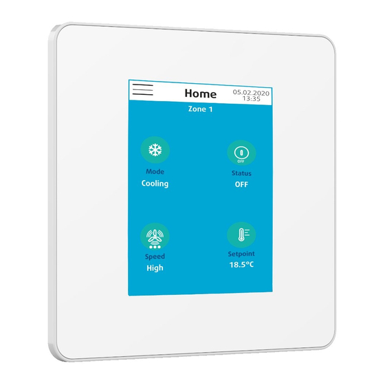
Page 25: Control Of Devices
7. CONTROL OF DEVICES can control all the devices by acting: on the zone on one device only ² ² with direct control of units direct control of a unit verification of operating parameters 05.02.2020 Home Menu Device 13:35 Fan coil , Address 1 Zone 1 Fan coil Fan coil , Address 2... -
Page 26: Fan Convector Unit B
24 SRC can act individually, like a remote control on: operating mode ² Fan coil Address 1 Fan coil Address 1 unit status ² Mode Remote air probe ventilation speed Cooling 0.0°C ² Status Water probe ambient setpoint ² 0.0°C... -
Page 27: Chillers And Hot Water Production Units
can act individually, like a remote control on: operating mode ² Fan coil Address 1 Fan coil Address 1 unit status ² Mode Auxiliary probe ventilation speed Cooling 0.0°C ² Status ambient setpoint ² It is also possible to check the different temperatures Speed measured by the: Auto... -
Page 28: Chiller B
26 SRC 7.2.2. CHILLER B is used to act for all the devices in the zone on the following: operating mode unit status ² ² Home 05.02.2020 Home 05.02.2020 Home 05.02.2020 Home 05.02.2020 13:35 13:35 13:35 13:35 Zone 1 Zone 1... -
Page 29: Heat Pump On Water Circuit
7.4. HEAT PUMP ON WATER CIRCUIT can act individually, like a remote control on: operating mode unit status ² ² Home 05.02.2020 Home 05.02.2020 Home 05.02.2020 Home 05.02.2020 13:35 13:35 13:35 13:35 Device 1 , Address 1 Device 1 , Address 1 Device 1 , Address 1 Device 1 , Address 1 Mode... -
Page 30: Alarm
28 SRC is used to act individually on the following: operating mode ² unit status ² ventilation speed ² ambient setpoint(s) ² Address 1 Address 1 WSHP WSHP in use/not in use Mode Air probe ² Auto 0.0°C It is also possible to check the temperature measured by... -
Page 31: Password Change
If you forget the new password, action by the after-sales service will be required. 10. SRC RESET This command resets the SRC. All created fields and addresses will be deleted, all the values displayed will be the default parameters. Settings... -
Page 32: In Case Of Warranty - Material Return Procedure
30 SRC 11. IN CASE OF WARRANTY - MATERIAL RETURN PROCEDURE Material must not be returned without permission of our After Sales Department. To return the material, contact your nearest sales office and ask for a "return form". The return form shall be sent with the returned material and shall contain all necessary information concerning the problem encountered. - Page 33 BROWN MARRON BLACK NOIR NEGRO SCHWARTZ NERO KIT SRC ROUGE ROSSO ROJO BLUE BLEU BLAU AZUL GREEN/YELL. GNYE VERT/JA. GIALLO/V. GRUN/G. VERDE/AM. PURPLE 50/60Hz VIOLET VIOLA VIOLETT VIOLETA 230V SE 4841 WIRING BY INSTALLER CABLAGE CLIENT OPTIONAL/OPTION D1 D2 230V...
- Page 34 As part of our ongoing product improvement programme, our products are subject to change without prior notice. Non contractual photos. Systemair AC SAS Route de Verneuil 27570 Tillières-sur-Avre FRANCE & : +33 (0)2 32 60 61 00 6 : +33 (0)2 32 32 55 13...
Need help?
Do you have a question about the SRC and is the answer not in the manual?
Questions and answers