Table of Contents
Advertisement
Installation/Maintenance
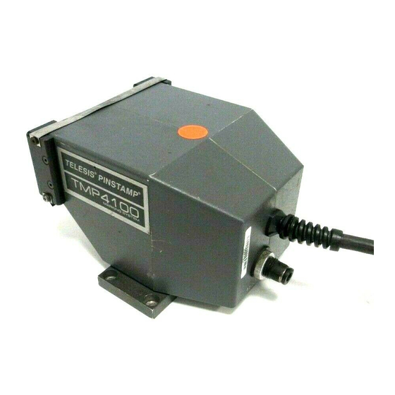
TMP4100-Series
PINSTAMP
This document contains installation and maintenance information
for the Telesis TMP4100 and TMP4100E hand-held markers and
the Telesis TMP4150 and TMP4155 fixture-mounted marking
heads. This document may be supplemented and kept current by
Change Notices and Revisions.
Document No. 33480 Rev. D.01
Telesis Technologies, Inc.
28181 River Drive
P.O. Box 1000
Circleville, Ohio 43113
®
Marking Head
September 2003
Change 1 – March 2004
Advertisement
Table of Contents

Subscribe to Our Youtube Channel
Related Manuals for Telesis PINSTAMP TMP4100 Series


Summary of Contents for Telesis PINSTAMP TMP4100 Series
- Page 1 PINSTAMP Marking Head This document contains installation and maintenance information for the Telesis TMP4100 and TMP4100E hand-held markers and the Telesis TMP4150 and TMP4155 fixture-mounted marking heads. This document may be supplemented and kept current by Change Notices and Revisions.
-
Page 3: List Of Effective Pages
TMP4100-Series Installation/Maintenance List of Effective Pages DATES OF MANUAL AND CHANGED PAGES First Issued......October 2000 Revision A ......September 2001 Revision B ........July 2002 Revision C .......August 2002 Revision D ......September 2003 Change D.01 ......March 2004 N O T E The portion of the text affected by the change is indicated by a vertical line in the outer margins of the page. - Page 4 TMP4100-Series Installation/Maintenance This page intentionally left blank. 33480D01.DOC Change 1...
-
Page 5: Foreword
In no event shall Telesis be liable for any incidental, indirect, special, or consequential damages whatsoever, including but not limited to lost profits, arising out of, or relating to this document or the information it contains, even if Telesis has been advised, has knowledge, or should have knowledge of the possibility of such damages. -
Page 6: Safety Summary
TMP4100-Series Installation/Maintenance Safety Summary The TMP4100-Series markers use high voltage power supplies and high pressure pneumatic supplies. Accordingly, there is some danger when working with, and near, Pinstamp marking machines. The ® following safety precautions should be observed at all times. ♦... -
Page 7: Table Of Contents
TMP4100-Series Installation/Maintenance Table of Contents PARAGRAPH PAGE List of Effective Pages .......................... Foreword ............................... Safety Summary............................ List of Illustrations ..........................List of Tables ............................Section 1 Installation Overview..........................Specifications ........................... 1.2.1 TMP4100 Marking Head....................1.2.2 TMP4100E Marking Head ....................1.2.3 TMP4150 and TMP4155 Marking Heads ................. - Page 8 Marker Standoff ......................... 2-15 2.8.3 TMP4100 Solenoid Valve....................2-16 2.8.4 TMP4100E Solenoid Valve ....................2-18 2.8.5 TMP4150 and TMP4155 Solenoid Valve................2-20 Reference Data ......................... 2-21 2.9.1 Replacement Parts......................2-21 2.9.2 Ordering Parts ........................2-23 2.9.3 Telesis Customer Support ....................2-23 33480D01.DOC...
- Page 9 TMP4100-Series Installation/Maintenance List of Illustrations FIGURE PAGE General Arrangement – TMP4100-Series Installation..............1-10 TMP4100 and TMP4100E Dimensions ..................1-13 TMP4150 and TMP4155 Mounting Details.................. 1-15 Cleaning the Filter/Regulator Bowl ....................Pin Cone Angle and Length ......................2-12 List of Tables TABLE PAGE Troubleshooting the Marking Head ....................
- Page 10 TMP4100-Series Installation/Maintenance This page intentionally left blank. viii 33480D01.DOC...
-
Page 11: Installation
TMP4100-Series Installation/Maintenance Section 1 Installation 1.1 OVERVIEW This section documents the installation of TMP4100, TMP4100E, TMP4150, and TMP4155 marking heads. The TMP4100, TMP4150, and TMP4155 heads contain a pneumatic pin that uses air pressure to drive the pin from and return the pin to the pin cartridge. The TMP4100E (electric) head uses no air pressure. The TMP4100E uses an electric solenoid to drive and an internal spring to assist pin return. -
Page 12: Specifications
TMP4100-Series Installation/Maintenance 1.2 SPECIFICATIONS The marking equipment design and specifications are subject to change without prior notice. 1.2.1 TMP4100 Marking Head Weight ........4.08 lb. (1.85 kg) marking head with handle 5.50 lb. (2.50 kg) marking head with handle and marker cable Dimensions ( .... -
Page 13: Tmp4150 And Tmp4155 Marking Heads
TMP4100-Series Installation/Maintenance 1.2.3 TMP4150 and TMP4155 Marking Heads Weight ........8.7 lb. (3.9 kg) marking head, brackets, and cable Dimensions ( ....9.89 x 5.12 x 4.96 in. (251 x 130 x 126 mm) with 25XL pin (w/o boot*) L x W x H 10.14 x 5.12 x 4.96 in. -
Page 14: Storage And Handling Requirements
TMP4100-Series Installation/Maintenance 1.2.4 Filter/Regulator Unit The TMP4100E does not employ a filter/regulator unit. It uses an electric solenoid to drive the TMP4100E: pin and an internal spring to assist pin return. The filter/regulator unit includes a regulator with a coarse filter and a pressure gauge to control the TMP4100: drive air. -
Page 15: Unpacking The Equipment
TMP4100-Series Installation/Maintenance 1.3 UNPACKING THE EQUIPMENT This section provides guidelines for receiving and unpacking the TMP4100-Series marking equipment. C A U T I O N If your equipment arrives during cold weather, allow the components to warm up for several hours before opening the containers. Exposing the equipment to room temperatures may cause condensation in the units. -
Page 16: Inspecting For Damage
TMP4100-Series Installation/Maintenance 1.3.2 Inspecting for Damage Place the components on a table and inspect each one for damage. Report any damage to your delivery service immediately. Inspect the marking head. ♦ Ensure the marking head is not dented or cracked. ♦... -
Page 17: General
TMP4100-Series Installation/Maintenance 1.4.1 General • A safety guard may be required to keep operators away from the moving marking TMP4150, TMP4155: head and impact pin. • A part-present switch may be installed to allow a only when a part is START PRINT TMP4150, TMP4155: in marking position. -
Page 18: Facility (Supply) Air
Air Flow. The cyclone effect (see above) cannot occur if there is little or no flow of air. Telesis markers use much less air at idle than when marking. So it’s during the idle time that the aerosol particles have a chance to cool and condense on the walls of the cartridge and pin. - Page 19 TMP4100-Series Installation/Maintenance Plumbing Factors. Another practice for obtaining clean, dry air is to ensure the equipment is not at the end of the air line. Plumb the air supply to go up (vertically) off the main air supply line, then down to the top of a tee. The stem of the tee should be horizontal and go to the marker.
-
Page 20: Installation Procedures
TMP4100-Series Installation/Maintenance 1.5 INSTALLATION PROCEDURES Perform the following procedures (in the order listed) to install the marking equipment. See Figure 1-1 for a general arrangement illustration. N O T E It is the responsibility of the installing agency to ensure the installation requirements are correctly implemented. -
Page 21: Marking Head Installation
TMP4100-Series Installation/Maintenance 1.5.1 Marking Head Installation Refer to Figure 1-1 for general arrangement. For hand-held units, refer to Figure 1-2 for dimensions. For fixture-mounted units, refer to Figure 1-3 for mounting hole dimensions and locations. TMP4100: To allow the marker cable to reach the controller, ensure the marking head location is within 4m (13 ft.) of the proposed controller location. - Page 22 TMP4150, TMP4155 Mounting Instructions Perform the following procedures to mount the TMP4150 and TMP4155 marking heads onto a standard Telesis tool stand or onto a customer-supplied fixture, as applicable. Telesis Tool Stand P/N 27200 Note: Mounting hardware for the marking head is supplied in the standard tool stand kit (26208).
- Page 23 TMP4100-Series Installation/Maintenance 1-13 33480D01.DOC...
- Page 24 TMP4100-Series Installation/Maintenance This page intentionally left blank. 1-14 33480D01.DOC...
- Page 25 TMP4100-Series Installation/Maintenance 1-15 33480D01.DOC...
-
Page 26: Filter/Regulator Unit Installation
TMP4100-Series Installation/Maintenance 1.5.2 Filter/Regulator Unit Installation The TMP4100E does not use air pressure to drive the marking pin. The following section does TMP4100E: not apply to the TMP4100E marker. TMP4100, TMP4150, TMP4155: To allow the air lines to reach the marking head, ensure the filter/regulator mounting location is within 12 ft. -
Page 27: Controller Installation
TMP4100-Series Installation/Maintenance 1.5.3 Controller Installation Refer to the Controller Installation/Maintenance Manual that was supplied with your marking system for the following procedures. Install the marking system controller. Perform the electrical and data connections. Perform the controller checkout. Proceed with Installation Adjustments. 1.5.4 Auxiliary Axis Equipment If the marker includes optional Z-axis (vertical axis) or Theta-axis (rotational axis) components, refer to the Auxiliary Axis Installation Supplement that was supplied with the optional equipment for specific installation... - Page 28 TMP4100-Series Installation/Maintenance This page intentionally left blank. 1-18 33480D01.DOC...
-
Page 29: Maintenance
This section provides troubleshooting, testing, repair, and replacement procedures for the marking head. Any additional troubleshooting, fault isolation, servicing, maintenance, or repair of TMP4100-Series marking head that is not explicitly contained in this document must be performed by repair agencies authorized by Telesis Technologies, Inc. -
Page 30: Cleaning Procedures
TMP4100-Series Installation/Maintenance 2.4 CLEANING PROCEDURES The following information is provided to clean the various marking head components. 2.4.1 Filter/Regulator Bowls The TMP4100E does not use a filter/regulator unit. The following section does not apply to the TMP4100E: TMP4100E marker. Perform the following procedure when cleaning is necessary. See Figure 2-1. TMP4100, TMP4150, TMP4155 Figure 2-1. -
Page 31: Impact Pin / Pin Cartridge
TMP4100-Series Installation/Maintenance 2.4.2 Impact Pin / Pin Cartridge Perform the following steps to clean the pin cartridge and impact pin. Remove the impact pin / pin cartridge from the marking head. (see replacement procedure) Clean the cartridge using isopropyl alcohol or dish washing detergent and water. The pins may be cleaned with solvent as long as they are wiped off completely and allowed to dry before being placed back into the cartridge. -
Page 32: Troubleshooting
If a defective component has been identified, refer to appropriate maintenance instructions to repair or replace the component. If these procedures fail to correct the problem, contact Telesis Customer Support. Table 2-1. Troubleshooting the Marking Head... - Page 33 TMP4100-Series Installation/Maintenance Table 2-1. Troubleshooting the Marking Head (continued) PROBLEM CORRECTIVE ACTION Marking pin fires but does not mark 1. Ensure the pin stroke does not exceed its maximum limit. Reduce the distance between the retracted pin and the marking surface as required. 2.
- Page 34 TMP4100-Series Installation/Maintenance Table 2-1. Troubleshooting the Marking Head (continued) PROBLEM CORRECTIVE ACTION Marker sounds as if motors are running, but no CAUTION motion in one or both axes Do not connect or disconnect the marker cable while the controller power is ON. Turn power off before connecting/disconnecting the cable.
- Page 35 TMP4100-Series Installation/Maintenance Table 2-1. Troubleshooting the Marking Head (continued) PROBLEM CORRECTIVE ACTION Message is cut off or truncated The message length may be too long to print within the marking window. Using the marking system software, edit the pattern object as required: 1.
- Page 36 TMP4100-Series Installation/Maintenance Table 2-1. Troubleshooting the Marking Head (continued) PROBLEM CORRECTIVE ACTION Impact depth is insufficient or inconsistent 1. Ensure the impact pin is not dull or broken. Sharpen or replace as required. 2. Ensure the pin cartridge bore is not worn. Replace if necessary 3.
- Page 37 TMP4100-Series Installation/Maintenance Table 2-1. Troubleshooting the Marking Head (continued) PROBLEM CORRECTIVE ACTION Indentation depth is inconsistent in a particular 1. TMP4100, TMP4150, TMP4155: The coiled Drive Air tubing may be area of the marking window. kinked or restricted when traversing. Inspect the tubing from the valve to the manifold for cracks, restrictions or crimps in the tubing.
-
Page 38: Testing Procedures
TMP4100-Series Installation/Maintenance 2.6 TESTING PROCEDURES This section provides reference tables to check the circuitry for TMP4100-Series marking heads. 2.6.1 Stepper Motor Resistance The following information is provided to check the resistance values of the stepper motor circuit. Remove electrical power from the marking system. Remove air pressure from the marking system. -
Page 39: Extension Cable Continuity
TMP4100-Series Installation/Maintenance 2.6.3 Extension Cable Continuity The following information is provided to check the continuity of the marking head extension cable, if used. The cable connects between the TMP4100-Series marker cable and the controller. Remove electrical power from the marking system. Remove air pressure from the marking system. -
Page 40: Repair Procedures
2.7 REPAIR PROCEDURES Authorized repair of the TMP4100-Series marking head is limited to impact pin reconditioning. Any other repair of the marking head must be performed by repair agencies authorized by Telesis Technologies, Inc. 2.7.1 Impact Pin Reconditioning Pin life depends largely on the type of material being marked, how hard or abrasive it is, and the required marking depth. - Page 41 TMP4100-Series Installation/Maintenance The recommended grinding wheels for the various pin material are listed below. The minimum pin lengths allow for only about a 3% reduction in the total length during reconditioning. Therefore, only the smallest amount of material necessary to obtain a sharp point should be removed. Several small “cuts” should be taken, instead of larger ones, to avoid removing more material than necessary and to avoid overheating the pin.
-
Page 42: Replacement Procedures
Authorized replacement of the TMP4100-Series marking head components are listed in the following paragraphs. Component replacement procedures not explicitly contained in this document must be performed by repair agencies authorized by Telesis Technologies, Inc. 2.8.1 Impact Pin / Pin Cartridge Follow the steps below to remove and replace the impact pin and/or the pin cartridge assembly. -
Page 43: Marker Standoff
TMP4100-Series Installation/Maintenance 2.8.2 Marker Standoff The TMP4150 and TMP4155 do not use a marker standoff. The following section does TMP4150, TMP4155: not apply to the TMP4150 or TMP4155 markers. Perform the following procedure to replace the standoffs mounted on the front of the TMP4100, TMP4100E: marking head. -
Page 44: Tmp4100 Solenoid Valve
TMP4100-Series Installation/Maintenance 2.8.3 TMP4100 Solenoid Valve Perform the following procedure to replace the TMP4100 solenoid valve. Removal Remove electrical power from the marking system. Remove air pressure from the marking system. Remove the standoffs. (see replacement procedure) Using a 2.5mm hex key, remove four M3-0.50 x 25 screws securing right cover to left cover. Separate covers and place right cover aside. - Page 45 TMP4100-Series Installation/Maintenance Installation Install the new solenoid valve assembly. Ensure the gasket is properly positioned. Route the solenoid wires toward the upper, backside of the X-axis motor and push the plugs onto limit board connectors J6 and J7. Install the marking unit into left cover and secure with three flat head screws. Connect the marking unit cable connector J2 to J1 on the limit board.
-
Page 46: Tmp4100E Solenoid Valve
TMP4100-Series Installation/Maintenance 2.8.4 TMP4100E Solenoid Valve Perform the following procedure to replace the TMP4100E solenoid valve. Removal Remove electrical power from the marking system. Remove the impact pin / pin cartridge from the marking head. (see replacement procedure) Remove the standoffs. (see replacement procedure) Using a 2.5mm hex key, remove four M3-0.50 x 25 screws securing right cover to left cover. - Page 47 TMP4100-Series Installation/Maintenance Verify the armature and shim(s) are in place prior to securing the solenoid. Align the holes and attach with two M3-.05 x 6mm flat head cap screws. C A U T I O N Do not pull the wires through from the backside of the cartridge base. Doing so might strip insulation from the wires and short the solenoid drivers.
-
Page 48: Tmp4150 And Tmp4155 Solenoid Valve
TMP4100-Series Installation/Maintenance 2.8.5 TMP4150 and TMP4155 Solenoid Valve Perform the following procedure to replace the TMP4150 or TMP4155 solenoid valve. Removal Remove electrical power from the marking system. Remove air pressure from the marking system. Remove the marking head cover: Lift up on the tabs of the latches located on the sides of the marker. -
Page 49: Reference Data
TMP4100-Series Installation/Maintenance 2.9 REFERENCE DATA The following information will assist you in obtaining components to maintain the marking head. 2.9.1 Replacement Parts Refer to Table 2-6 for a list of replaceable components and their part numbers. Additional tables in this section list impact pins and pin cartridge assemblies that may be used with the TMP4100-Series markers. - Page 50 TMP4100-Series Installation/Maintenance Table 2-9. Impact Pins PART NO. DESCRIPTION TMP4100 TMP4100E TMP4150 TMP4155 ● ● ● 14060 Pin, Impact, 25XL, Carbide, 22° ● ● ● 14061 Pin, Impact, 25XL, Carbide, 30° ● ● ● 14062 Pin, Impact, 25XL, Carbide, 45° ●...
-
Page 51: Ordering Parts
Service Contracts - As part of your Service Contract, you receive periodic maintenance and quick on-site customer support if a problem should occur. Factory Service - Telesis Customer Support can repair defective parts in our factory to save you money. Contact us for more information on any of these services. - Page 52 TMP4100-Series Installation/Maintenance This page intentionally left blank. 2-24 33480D01.DOC...
- Page 53 TMP4100-Series Installation/Maintenance Appendix A Material Safety Data Sheets This Appendix contains Material Safety Data Sheets (MSDS) for carbide and steel impact pins. The impact pins are used by the TMP4100-Series marking heads for imprinting messages into various materials. Read the MSDS sheets prior to reconditioning pins to become familiar with potential reconditioning hazards.
- Page 54 Appendix A This page intentionally left blank. 33480D01.DOC...
- Page 55 TMP4100-Series Installation/Maintenance MATERIAL SAFETY DATA SHEET CARBIDE PINS 1. PRODUCT DEFINITION CHEMICAL NAME: TRADE NAME & SYNONYMS: Cemented carbide product All Carbide Grades CHEMICAL FAMILY: MOLECULAR WEIGHT: Refactory Metal Carbide Varies with grade 2. HAZARDOUS INGREDIENTS MATERIAL BY WEIGHT OSHA PEL ACGIH TLV Tungsten Carbide 12070-12-1...
- Page 56 Appendix A 4. FIRE AND EXPLOSION HAZARD DATA Flash Point: Test Method Used: Auto-ignition Temperature: Hard cemented carbide product is not a fire hazard. Dusts generated in grinding operations may ignite if allowed to accumulate and are subjected to an ignition source. Flammable Limits: LEL: UEL:...
- Page 57 TMP4100-Series Installation/Maintenance 5. HEALTH HAZARD DATA (continued) Carcinogenicity - The National Toxicology Program (NTP) found there was sufficient evidence of carcinogenicity of nickel in experimental animals and limited evidence for the carcinogenicity of nickel in humans. The International Agency for Research on Cancer (IARC) found there was inadequate evidence that metallic cobalt and metallic nickel are carcinogenic to humans, but since there was sufficient evidence that they carcinogenic to animals, IARC concluded that metallic cobalt and metallic nickel are possibly carcinogenic to humans.
- Page 58 (740) 477-5000 (ask for Customer Service) (740) 477-5001 (FAX) Although Telesis has attempted to provide accurate information herein, Telesis makes no representation regarding the accuracy or completeness of the information and assumes no liability for any loss, damage or injury of any kind which may result from or arise out of the use of or reliance on the information by any person.
- Page 59 TMP4100-Series Installation/Maintenance MATERIAL SAFETY DATA SHEET STEEL PINS 1. PRODUCT DEFINITION STEEL PINS DATE OF PREPARATION: November 1, 1985 PRODUCT NAME: A Supplemental Chemistry Sheet will be issued for each grade shipped to each customer. See Section 2. 2. HAZARDOUS INGREDIENTS MATERIAL CAS NUMBER MATERIAL...
- Page 60 Appendix A 4. FIRE AND EXPLOSION HAZARD DATA Flash Point: None Fire Point: None This product is a noncombustible metal. See Appendix A for any applicable Fire and Explosion Data for each element. 5. HEALTH HAZARD DATA A. GENERAL COMMENTS We do not consider this product in the form it is sold to constitute a physical hazard or a health hazard.
- Page 61 TMP4100-Series Installation/Maintenance 6. REACTIVITY DATA Stability: Unstable X Stable Hazardous Polymerization: May Occur X Will Not Occur Incompatibility: Reacts with strong acids to generate hydrogen gas. Materials to Avoid: Strong acids and oxidizers. Hazardous Decomposition Products: Metallic oxides. Conditions to Avoid: Avoid generation of airborne dust and fumes. 7.
- Page 62 (740) 477-5000 (ask for Customer Service) (740) 477-5001 (FAX) Although Telesis has attempted to provide accurate information herein, Telesis makes no representation regarding the accuracy or completeness of the information and assumes no liability for any loss, damage or injury of any kind which may result from or arise out of the use of or reliance on the information by any person.
Need help?
Do you have a question about the PINSTAMP TMP4100 Series and is the answer not in the manual?
Questions and answers