Advertisement
Quick Links
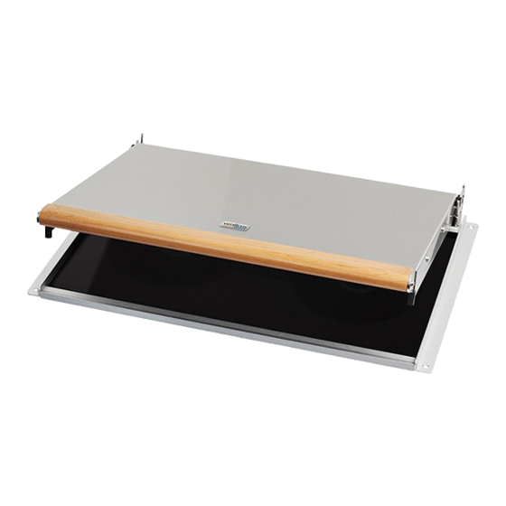
Quick installation instructions for
blower lid 270 with surface kit 110
Surface installation kit 110:
• Delivery includes following items:
1. back cover sheet,
2. flexible exhaust pipe, L=520mm,
3. ceramic isolation sleeve,
4. plastic sleeve Ø8x24.5mm,
5. hose clip DIN 3017-1 20/32mm,
6. Screw DIN 7985 M4x16 A2,
7. Screw DIN 7985 M4x35 A2,
Wallas-Marin Oy, Kärrykatu 4, FIN-20780 Kaarina Finland
Tel. +358-(0)2-412 0500 Fax +358-(0)2-412 0510
Business ID: 1999776 - 0. Registered place of business Helsinki
Instructions
4.4.2007
1 pce
1 pce
1 pce
2 pcs
3 pcs
4 pcs
2 pcs
Advertisement

Subscribe to Our Youtube Channel
Related Manuals for wallas 270

Summary of Contents for wallas 270
- Page 1 Instructions 4.4.2007 Quick installation instructions for blower lid 270 with surface kit 110 Surface installation kit 110: • Delivery includes following items: 1. back cover sheet, 1 pce 2. flexible exhaust pipe, L=520mm, 1 pce 3. ceramic isolation sleeve, 1 pce 4.
- Page 2 • Open frame fixing screws, if necessary (see note at page 6) Open.. Frame fixing screws Remove unnecessary parts.. • Open four screws [1] • .. and remove the back profile [2]. • Save items, they are not used with blower lid 270.
- Page 4 Installation of 270 blower unit: • Put the blower unit [3] between the profiles • And tighten M4x8 screws (4pcs) [4] (delivered with blower unit)
- Page 5 Connect the cable between 85DU and 270: • Remove shortcut piece and connect the blower cable [5] to the terminal • Fix the cable to the bracket [6] with a cable tie (delivered with 270). Please assure that the cable will not contact the tangential blower.
- Page 6 NOTE: The installation kit may be used without the back side exit, if there exists a option to install exhaust pipe i.e. vertically through the table surface. In that case, you may jump to the section Modify the existing surface installation case.
- Page 7 • Put the remaining exhaust pipe on the sleeve. Push the third clamp [9] tightly against the blower unit back sheet and tighten the screw. Assure that the aluminum sleeve [10] is stationary.
- Page 8 • Open four screws [11] from both ends. • And remove the back profiles [12]. • Save items, they are not used with blower lid 270 Put the stove & blower unit to its place: • Please careful with the stove: as both back profiles are missing, if the...
- Page 9 Tighten.. Add the back sheet: • Put the back cover on its place and tighten four M4x12 screws M4x12...
- Page 10 Final installation: • Reconnect the power cable and fuel hose • Put the stove on its place and tighten four screws Tighten .. • Connect the rest of the exhaust pipe to the sleeve • Slide the lid to hinge profile [13] and •...
Need help?
Do you have a question about the 270 and is the answer not in the manual?
Questions and answers