
Related Manuals for ITW Diagraph PA/6000

Summary of Contents for ITW Diagraph PA/6000
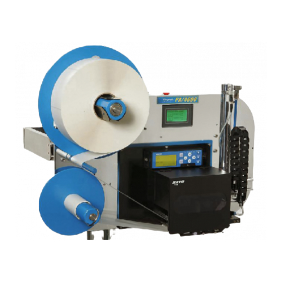
- Page 1 PA/6000 PA/6000 PA/4600 PA/4600 PPLICATOR RINTER - PPLICATOR RINTER - 4600-010 Revision G...
- Page 2 Diagraph - an ITW Company PA/4600 & PA/6000 User Manual Diagraph, an ITW company, continually improves its products, and reserves the right to change or discon- tinue specifications and designs shown in this manual without notice and without incurring obligation.
-
Page 3: Product Safety
This product meets the requirements of CAN/CSA-22.2 NO.60950-00 * UL 60950 using Diagraph an ITW Company approved items. Units are only tested and qualified with Diagraph an ITW Company approved parts and accessories. Use of other parts or accessories may introduce potential risks that Diagraph an ITW Company can assume no liability for. -
Page 4: Document Conventions
Warranty Information The PA/4600 and PA/6000 systems, including all components unless otherwise specified, carry a limited warranty. For all warranty terms and conditions, contact Diagraph, an ITW Company, for a complete copy of the Limited Warranty Statement. Introduction Page 3... -
Page 5: Specifications
Diagraph - an ITW Company PA/4600 & PA/6000 User Manual Specifications General Specifications Category Parameter Dimensions 31 in. (79 cm) L x 23 in. (58.5 cm) H x (with Yoke) 25 in. (63.5 cm) D Weight 90 lbs (41 ) (includes yoke, no stand) ±1.6 mm... -
Page 6: Minimum Maximum
Diagraph - an ITW Company PA/4600 & PA/6000 User Manual Mechanical Specifications - Tamp System Category Nominal Minimum Maximum Incoming Air Pressure 60 - 100 PSI 40 PSI 125 PSI Tamp Cylinder Pressure 30 - 50 PSI 20 PSI 80 PSI... -
Page 7: System Modules
Diagraph - an ITW Company PA/4600 & PA/6000 User Manual 2.0 System Modules Mechanical SubSystem Unwind P/N: 4600-605 The unwind is designed to capture supply rolls up to 14 inches in diameter, with 3 inch cores. This subsystem uses a hub‐based fin design to capture the supply roll without ... - Page 8 Diagraph - an ITW Company PA/4600 & PA/6000 User Manual Stand P/N: 6160-329 The stand holds the yoke assembly of the PA/ 4600 or PA/6000, and allows the system to be orientated in a variety of positions to suit application requirements. The stand employs a hand crank to set vertical position, and a series of mounting points for items such as: ...
- Page 9 Diagraph - an ITW Company PA/4600 & PA/6000 User Manual Inlet Filter/Regulator/Shutoff P/N: 4600-705 The inlet air filtration provides an OSHA‐ approved shutoff, with lock‐out, and a pressure regulator. It uses a 5 micron filter element and automatically purges condensation trapped in the filter bowl. The ...
- Page 10 Diagraph - an ITW Company PA/4600 & PA/6000 User Manual Printer P/N: 4600-800 PA/4600 Models Only The only printer selection for the PA/4600 is the SATO Lt 408. The Lt 408 is a medium‐ duty print engine that shares the same format language and commands as the venerable SATO 8485Se. The Lt 408 is capable of using either a ribbon for thermal transfer printing ...
- Page 11 Diagraph - an ITW Company PA/4600 & PA/6000 User Manual Product Sensor P/N: 4600-900 The product sensor is an infrared, diffused light model, capable of sensing objects at distances up to 3 ft. (900 mm). The sensor has two LED’s, one is a yellow detection indicator and the other serves two purposes. If no object is currently detected, the green ...
- Page 12 Diagraph - an ITW Company PA/4600 & PA/6000 User Manual Pressure Sensor P/N: 4600-905 The pressure sensor has several great features, and still maintains a simplicity in design. The sensor should not require adjustments since the threshold levels are set at the factory. The sensor constantly monitors pressure and triggers an error on the system if the air pressure drops below the ...
- Page 13 Diagraph - an ITW Company PA/4600 & PA/6000 User Manual 3.0 Setup Step 1 - Determine the System Orientation Goal: Determine the best machine orientation for application. The PA/4600 and PA/6000 are capable of rotating and pitching about various axes to accommodate a wide range of label placement opportunities.
-
Page 14: Compressed Air
Diagraph - an ITW Company PA/4600 & PA/6000 User Manual Step 2 - Connect Compressed Air and AC Power Goal: Provide the unit with clean, dry compressed air and connect the power supply to a noise-free AC power line. Note: The system employs an automatic drain air filter, which will remove most of the condensation in the incoming pneumatic line. - Page 15 Diagraph - an ITW Company PA/4600 & PA/6000 User Manual Step 3 - Mount and Adjust the Product Detector Goal: Determine which mounting location is ideal, either on the baseplate or on the conveyor system. Goal: Adjust the sensor to detect just the product, and ignore background objects, such as forklift trucks, personnel, or other objects that may pass in front of the sensor’s view.
- Page 16 Diagraph - an ITW Company PA/4600 & PA/6000 User Manual Step 4 - Configure the One Time Settings (OTS) Goal: Enter the One Time Settings screens and select the configuration of this particular system. Note: Most of these items were determined when the unit was assembled; so only configurations that have changed require this adjustment.
- Page 17 Diagraph - an ITW Company PA/4600 & PA/6000 User Manual Step 6 - Enter Values for the Job Settings Goal: Enter Job setting values to control specific aspects of the product label application Map: Beginning in the Offline mode, press the Settings button. From the Settings Menu, which...
- Page 18 Diagraph - an ITW Company PA/4600 & PA/6000 User Manual ** Step 8 - Load the Media -PA/4600 Models Goal: Correctly load the label supply and web the applicator and printer. Goal: Correctly load the ribbon, if using Thermal Transfer mode, inside the printer.
- Page 19 Diagraph - an ITW Company PA/4600 & PA/6000 User Manual ** Step 8 - Load the Media -PA/6000 Models Goal: Correctly load the label supply and web the applicator and printer. Goal: Correctly load the ribbon, if using Thermal Transfer mode, inside the printer.
- Page 20 Diagraph - an ITW Company PA/4600 & PA/6000 User Manual Step 9 - Adjust the Tamp Pad Position Goal: Slide the tamp cylinder module across the dovetail track to the correct position in front of the printer, this will be approximately 1/8th of an inch from the peel blade edge.
- Page 21 Diagraph - an ITW Company PA/4600 & PA/6000 User Manual Step 10 - Set the Tamp Pneumatic Controls Goal: Adjust the optimum tamp pad travel to ensure label transfer to the product These adjustments will require an initial setup and a final adjustment, as other parameters are changed.
- Page 22 Diagraph - an ITW Company PA/4600 & PA/6000 User Manual Step 11 - Set the Vacuum, Air, and Blow Values Goal: Set the air assist flow control, vacuum and blow pressure, and blow flow control. •••• Sub-Step (a) •••• The air assist is used to guide the label toward the tamp pad while being dispensed from the printer.
- Page 23 Diagraph - an ITW Company PA/4600 & PA/6000 User Manual Step 12 - Test Print Goal: Verify communications between the applicator and the printer Goal: Optimize the printer image offset on the label, print darkness, presentation of the label out of the printer (pitch), and print quality.
- Page 24 Diagraph - an ITW Company PA/4600 & PA/6000 User Manual Step 13 - Create a Format and Download Goal: Create a simple format, set the correct communications parameters, and send a format down to the system. Although label software programs will differ in look and functionality, there are some key similarities.
- Page 25 Diagraph - an ITW Company PA/4600 & PA/6000 User Manual Step 14 - Test Tamp Goal: Make fine adjustments to optimize the performance of the system once running. •••• Sub-Step (a) •••• Tamp Duration (2nd Tamp Duration) The tamp duration, and 2nd tamp duration (if the Apply Mode is a dual action type), can be adjusted...
- Page 26 Diagraph - an ITW Company PA/4600 & PA/6000 User Manual Step 15 - Make Final Adjustments Goal: Make fine adjustments to optimize the performance of the system once running •••• Sub-Step (a) •••• Product Delay (Second Product Delay) The product delay controls the time between the product detector trigger and start of the application cycle.
-
Page 27: User Interface
Diagraph - an ITW Company PA/4600 & PA/6000 User Manual 4.0 User Interface One Time Setting (OTS) Screens Map: Power On Note: Can only be entered from power on transition Screen Functionality If the Label Present sensor is installed on the unit, press the button below the text until it displays “Yes”. -
Page 28: System Settings Screens
Diagraph - an ITW Company PA/4600 & PA/6000 User Manual System Settings Screens Map: Screen Functionality The system can be selected to Tamp, Tamp/Blow, or Blow. In addition, there are selections for having a double apply for applications such as Front Apply Swing Arms (FASA) or dual label per product. - Page 29 Diagraph - an ITW Company PA/4600 & PA/6000 User Manual Job Settings Screens Map: Note: Can only be entered from an offline state Screen Functionality From this screen the user can switch jobs, thus recalling multiple job settings at once. The system stores up to 60 jobs in non-volatile memory.
- Page 30 Diagraph - an ITW Company PA/4600 & PA/6000 User Manual Screen Functionality page 26 If the optional auto-retract sensor is installed (OTS screens, this screen will be visible for adjustments. The auto-retract sensor will detect the product surface before contact. This allows the lightest...
-
Page 31: Diagnostic Screens
Diagraph - an ITW Company PA/4600 & PA/6000 User Manual Diagnostic Screens Map: Screen Functionality From the main Diagnostics screen, the individual categories of I/O, Rewind, Printer, Sensors, and Pneumatics can be tested. Once the Diagnostic menu is entered, the warning tower and discrete outputs will begin to toggle automatically to test these outputs. - Page 32 Diagraph - an ITW Company PA/4600 & PA/6000 User Manual Screen Functionality The Sensor Diagnostic screen shows all of the main system sensors on one screen. An indicator with a black background is active, while a white background indicates inactive. The sensor names are limited to three characters, with the meanings listed here: •...
- Page 33 Diagraph - an ITW Company PA/4600 & PA/6000 User Manual Discrete I/O Map: Note: This only applies to units equipped with the optional 6145-405 Discrete I/O Kit Note: If no card is installed, all settings must be None for proper operation...
- Page 34 Diagraph - an ITW Company PA/4600 & PA/6000 User Manual Screen Functionality Use this menu to map the desired input event to the input port number. The selection choices are identical for each of the inputs 1 through 4 (Input 1 shown at left). Multiple inputs can be assigned to a single event, thus logically ‘ANDing’...
-
Page 35: Information Screens
Diagraph - an ITW Company PA/4600 & PA/6000 User Manual Information Screens Map: Note: Information screens can be entered while running (online) or offline. The below columns indicate the menu structure for the given information area: Web Path System Parts... - Page 36 Diagraph - an ITW Company PA/4600 & PA/6000 User Manual Power On/Off Screens Map: Screen Functionality By pressing the Enter Standby button the unit goes offline and devices on the switched 24 VDC supply are turned off. Once off, the screen will transition to the next following screen for turning it back on.
-
Page 37: Troubleshooting
Diagraph - an ITW Company PA/4600 & PA/6000 User Manual 5.0 Troubleshooting System Warnings Note: Any of the following warnings will be displayed on the screen, and the system will continue operation. This line will change as the status or warning is... -
Page 38: System Errors
Diagraph - an ITW Company PA/4600 & PA/6000 User Manual System Errors Note: Any of the following errors will place the unit in offline, thus stopping operation Screen Screen Screen E01 ‐ Printer E02 ‐ Repeat Print Cycle E03 ‐ Repeat Tamp Cycle E04 ‐ Cylinder Not Home E05 ‐ Ribbon Supply Out E06 ‐ Air Pressure Out E07 ‐ Rewind Tension E08 ‐ Label Supply Out E09 ‐ Second Apply Error E10 ‐ External Input... - Page 39 Diagraph - an ITW Company PA/4600 & PA/6000 User Manual Problem - Solution Matrix GENERAL Problem Cause Correction Multiple labels are fed out of Label Present is installed, but Adjust the web guides in the the printer, without a pause ...
- Page 40 Diagraph - an ITW Company PA/4600 & PA/6000 User Manual TAMP ISSUES Problem Cause Correction Label is on the tamp pad, but Product detector not triggered Verify in Diagnostics Menu that tamp cylinder does not fire by product the product detector can repeatedly detect the product. Adjust sensor as necessary Apply trigger occurred before ...
- Page 41 Diagraph - an ITW Company PA/4600 & PA/6000 User Manual Problem Cause Correction Label buckles on the tamp pad. Vacuum set too high Decrease vacuum in 5 psi increments until label lays flat on the pad. Tamp pad vacuum channels are The first column of holes should incorrectly ported be open, matching the width of the label. Last column of holes ...
- Page 42 Diagraph - an ITW Company PA/4600 & PA/6000 User Manual Catch Problems Before They Cause Downtime Air Volume (CFM) Problems Air pressure is the main consideration when connecting a machine requiring compressed air, but air volume (measured in cubic feet per minute) is just as important for regular operation. An elec- trical analogy would be: the air pressure can be thought of as voltage and the air volume can be thought of as electrical current.
-
Page 43: Maintenance Schedule
Diagraph - an ITW Company PA/4600 & PA/6000 User Manual 6.0 Maintenance Maintenance Schedule Maintenance Schedule Chart Daily Monthly Every Two Years √ Clean Printer Feed Rollers √ Replace Printer Feed Rollers √ Replace Printer Peel Blade √ Clean Label Present and Auto-Retract Sensors (if present) √... -
Page 44: Recommended Spare Parts List
Diagraph - an ITW Company PA/4600 & PA/6000 User Manual Recommended Spare Parts List Part Number Description DOCUMENTATION 4600‐010 PA/4600 & PA/6000 User Manual 4600‐015 Service Tool Software SATO Lt408 PRINTER 4600‐800 SATO Lt 408 Print Engine (Entire Printer) 4600‐810 SATO Lt 408 Print Head 4600‐811 SATO Lt 408 Platen Roller Assy 4600‐812 SATO Lt 408 Feed Roller Assy 4600‐813 SATO Lt 408 Ribbon Roller Assy 4600‐814 SATO Lt 408 Gap Sensor Assy. 4600‐815 SATO Lt 408 Main PCB 4600‐816 SATO Lt 408 Motor Drive PCB... - Page 45 Diagraph - an ITW Company PA/4600 & PA/6000 User Manual Part Number Description PA/4600 and PA/6000 4600‐521 Power Supply 4600‐643 Unwind Dancer Arm Spindle 4600‐200 MCA User Interface Touch Screen LCD 4600‐951 Main MCU Board Assembly 4600‐500 Main Controller Assembly III (MCA III) Includes: MCU Board, Interface Board, User Interface, Enclosure 4600‐503 Rewind BLDC Motor 4600‐950 MAINTENANCE KIT: Wear Items Set Includes: (2) Rewind Belts, (3) Spindles, (2/ea.) ...
- Page 46 Diagraph - an ITW Company PA/4600 & PA/6000 User Manual Assembly Views and Part Numbers Maintenance Page 45...
- Page 47 Diagraph - an ITW Company PA/4600 & PA/6000 User Manual Maintenance Page 46...
- Page 48 Diagraph - an ITW Company PA/4600 & PA/6000 User Manual Maintenance Page 47...
- Page 49 Diagraph - an ITW Company PA/4600 & PA/6000 User Manual Maintenance Page 48...
-
Page 50: Product Detector
Diagraph - an ITW Company PA/4600 & PA/6000 User Manual 7.0 Connection Port Information Product Detector J2, J3 DB9 Female Pin Description Pins 1, 2 Pin 3 Ground Pins 4, 5 Pin 6 +24 VDC Supply Pin 7 Pin 8 Product Detector Input Pin 9 Auxiliary Port Pin-Out J4 DB9 Male Pin Description Pin 1,2 Pin 3 Ground Pin 4... - Page 51 Diagraph - an ITW Company PA/4600 & PA/6000 User Manual Warning Tower Pin-Out J4 DB9 Female Pin Description Pin 1, 2, 3 Pin 4 Red (Ground Switched) Pin 5 Yellow (Ground Switched) Pin 6 + 24 VDC Supply Pin 7 Green (Ground Switched) Pin 8,9 Serial Communication Pin-Out J1 DB25 Female Pin Description Pin 1 Shield Ground Pin 2 Receive Pin 3 Transmit Pin 4...
-
Page 52: Pressure Sensor Setup
Diagraph - an ITW Company PA/4600 & PA/6000 User Manual 8.0 Pressure Sensor Adjustment Pressure Sensor Setup The Festo pressure sensor should be set at the factory, but it may be necessary to change settings on occasion. The sensor is used in a normally open mode, where the absence of proper air pressure opens the sensor’s contacts,... -
Page 53: Declaration Of Conformity
Diagraph - an ITW Company PA/4600 & PA/6000 User Manual 9.0 Declaration of Conformity DECLARATION OF CONFORMITY Diagraph, an ITW Company, hereby declares that the equipment specified below has been tested and found compliant to the following directives and standards- Directives: Standards: •...
Need help?
Do you have a question about the Diagraph PA/6000 and is the answer not in the manual?
Questions and answers