Table of Contents
Advertisement
Quick Links
Advertisement
Chapters
Table of Contents

Related Manuals for PURGE SOLUTIONS CYCLOPS Z

Summary of Contents for PURGE SOLUTIONS CYCLOPS Z
- Page 1 CYCLOPS Z – Purge Indicator IOM Manual...
- Page 2 This page intentionally left blank...
- Page 3 592 Avenue E 1/2, Alvin, Texas 77511 USA Phone: 832-368-7166 Fax: 281-824-4418 E-mail: info@purgesolutions.com Web site: http://www.purgesolutions.com Release Date: 12-August-2002 Document Number: DO-10011-X © Copyright 2002 by Purge Solutions, Inc. All rights reserved Revision Record Rev. Description Date Initial Release...
- Page 4 Disclaimer: Purge Solutions, Inc. makes every effort to ensure the accuracy and completeness of this manual. However, we cannot be responsible for errors, omissions, or any loss of data as the results of errors or omissions.
-
Page 5: Table Of Contents
Table of Contents Legal Notices and Revision History Inside front cover Section 1 Section 5 How To Use This Manual Start Up Procedures Safety Considerations Continuous Dilution Label Definition Table Explosive Gas Locating Information Applications General Safety Continuous Dilution General Precautions Combustible Dust Electrical Power Applications... -
Page 7: How To Use This Manual
Section 1 How to Use This IOM Manual Safety Considerations: This chapter includes important information that must be read and understood by all persons installing, using, or maintaining this equipment. While this IOM Manual is designed to aid personnel in the correct and safe installation, operation, and maintenance of the systems described. -
Page 8: Locating Information
The following symbols are used throughout this IOM Manual to alert users to potential hazards or important information. Failure to heed the warnings and cautions listed herein can lead to injury and equipment damage. D o c u m e n t L a b e l D e f i n i t i o n s U s e d t o I n d i c a t e P o t e n t i a l H a z a r d s Symbol Label... -
Page 9: General Precautions
WARNING: Deviation from the specified instruction or procedure steps can result in injury to personnel, equipment malfunction and / or equipment damage. WARNING: Return unit to factory for any repairs or replacement of parts, customer not permitted. This will void all warranties and hazardous area certification(s). -
Page 10: Electrical Power
____ MINUTES AFTER REMOVING POWER. Electrical Power: The CYCLOPS Z – Purge Indicator uses AC power of 115 or 230 volts and DC power of 12 or 24. The AC power is converted to DC. Appropriate precautions must be taken to prevent sparks that may ignite combustible materials that may be present in the Purge Indicator’s environment. -
Page 11: Conditions Of Safe Use
Purge & Pressurization System Conditions of Safe Use: CAUTION: The safe handling and operation of a purge and pressurization system requires basic knowledge of safety standards with additional training and experience to work on explosion protection equipment. CAUTION: Applicable permits must be obtained and appropriate precautions must be taken to prevent possible injury to personnel or equipment damage when installing or maintaining this equipment. -
Page 12: Specifications
Section 2 Specifications F e a t u r e s a n d C e r t i f i c a t i o n s Certified for installation and use in ATEX, IECEx and CE Marked II 3G Ex ec ic [pzc] IIC T6 Gc -40°C Ta +65°C, Zone 2 gas hazardous areas II 3D Ex ic [pzc] tc IIIC T79°C Dc IP66 -40°C ... -
Page 13: Utility Requirements
Protective Gas Supply Quality Water and oil-free, - 40°F (- 40°C) dew point, particles 5µ, ISA grade hydrocarbon free CYCLOPS Z – Purge Indicator Power Input / Consumption 0.5 Watts maximum Supply Voltage to 12 Volt model: 12 VDC, polarity protected CYCLOPS Z –... -
Page 14: Model Number Matrix
WARNING: Do not overpressure enclosure as this could damage or change factory setting of CYCLOPS Z – Purge Indicator pressure switch. Pressure switch proof pressure is 4 psi (0.27 bar). C Y C L O P S Z – P u r g e I n d i c a t o r... -
Page 15: Introduction
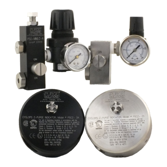
The CYCLOPS Z – Purge Indicator is used to provide safe monitoring of electrical equipment in Division 2, Zone 2 and Zone 22 hazardous locations, which can be used to prevent the possibility of fire or explosion inside the panel of energized electrical equipment. - Page 16 H O (1.25 mbar) for combustible dust atmospheres in any pressurized enclosure the CYCLOPS Z – Purge Indicator will alarm. For proper selection of components for your purge and pressurization application, refer to the Purge System Selection Wizard, which can be found on the home page of our web site www.purgesolutions.com.
- Page 17 Enclosures can be fabricated from 304 or 316 stainless steel, powder coated carbon steel or aluminum with all seams continuously welded and ground before finish is applied. Contact your local Purge Solutions, Inc. representative or the factory for sizing of system and installation information.
- Page 18 Contract. The Buyer shall not hold Purge Solutions, Inc. responsible for any delay or damages suffered by the Buyer by reason of any delay due to fires, strikes, riots, Acts of God, priorities, Government orders or restrictions, delays by suppliers or materials or parts, inability to obtain suitable and sufficient labor and / or any other unavoidable contingencies beyond the control of Purge Solutions, Inc.
-
Page 19: Indicator Installation Procedure
ATEX, CEC, IECEx, NEC and NFPA 496 standards. Indicator Installation Procedures: Review all of the material in this IOM Manual prior to installing the CYCLOPS Z – Purge Indicator to the enclosure it will be monitoring. If you have any questions, please contact your local Purge Solutions, Inc. - Page 20 NOTE: Purge / Pressurization Systems Recommended Connections for Single Enclosure are as follows: 1. Purge / pressurization system should be installed for best ease of viewing any system pressure gauges and / or visual alarms. 2. All tubing, piping and fittings should be selected and used that are suitable for the location they will be installed, used and protected from damage.
- Page 21 NOTE: Purge / Pressurization Systems Recommended Connections for Multiple Enclosures will include the recommendations for single enclosure plus the following: 1. Enclosures in series should be connected from smallest to largest enclosure. 2. Connections between enclosures should be properly sized to allow proper operation of purge / pressurization system and proper purge gas flow through enclosures.
- Page 22 NOTE: Purge Pressurization Systems Recommended Enclosure Installation for Hazardous Areas with Flammable Gasses or Vapors that are Lighter than Air are as follows: 1. The purge gas inlet supply connection should enter the enclosure near the bottom corner of the enclosure. 2.
- Page 23 NOTE: Purge / Pressurization Systems Recommended Enclosure Installation for Hazardous Areas with Flammable Gasses or Vapors that are Heavier than Air are as follows: 1. The purge gas inlet supply connection should enter the enclosure near the top corner of the enclosure. 2.
- Page 25 Step 4: Use Mounting Hole Template drawing number DO-11008-C to accurately locate the mounting holes. Use the Mounting Hole Template to draw and print a 1 to 1 scale drawing. Tape the 1 to 1 drawing to the outside of enclosure. The required hole locations can then be transferred and / or marked using the centers of the holes as shown on the 1 to 1 drawing.
- Page 26 Step 6: Before mounting the CYCLOPS Z – Purge Indicator install the o-ring provided into its appropriate groove. Next, line up CYCLOPS Z – Purge Indicator on the outside of enclosure, aligning the CYCLOPS Z – Purge Indicator to the mounting holes produced in Step 5.
- Page 27 Electrical Supply Power Installation:...
- Page 28 Step 8: Connect a minimum 16 AWG, stranded, three-conductor wire; refer to Power Source Specifications for power to the CYCLOPS Z – Purge Indicator. Refer to Wiring Diagram drawing number DO-11009-F for wire terminal strip locations. NOTE Refer to Power Source Specifications, Power Connection tables and Wiring Diagram number DO-11009-F for connecting power to the CYCLOPS Z –...
-
Page 29: Terminal Number Terminal Block
Dry Contact Alarm Signal Installation: Step 9: Connect a minimum 20 AWG, stranded, two-conductor wire; refer to Alarm Source Specifications for alarm signal to the CYCLOPS Z – Purge Indicator. Use Wiring Diagram drawing number DO-11009-F for wire terminal strip locations. - Page 30 Review all the material in this IOM Manual prior to installing any Protective Gas Inlet Kit. If you have any questions, please contact your local Purge Solutions, Inc. representative or the factory; refer to Getting Help page 55 or view installation video, which can be found on our web site www.purgesolutions.com.
-
Page 31: Protective Gas Inlet Kit
Step 7: For Continuous Dilution Protective Gas Inlet Kit use mounting fitting with O-ring and #10-32 screw with sealing washer or for Manual Leakage Compensation Protective Gas Inlet Kit use the mounting fittings with O-rings to mount the Protective Gas Inlet Kit to enclosure. -
Page 36: Back-Up Exhaust Vent Installation Procedure
Review all the material in this IOM Manual prior to installing any Back – Up Exhaust Vent. If you have any questions, please contact your local Purge Solutions, Inc. representative or the factory; refer to Getting Help page 55. Refer to Installation Flow Diagrams drawing numbers DO-11007-J-1 through 4, refer to pages 14 through 17. -
Page 43: Startup Procedures
Section 5 Startup Procedures The following steps should be performed when initially starting up a Purge Solutions, Inc. Type Z Purge and Pressurization System. WARNING: Failure to heed the following information may lead to injury of personnel and / or equipment damage. -
Page 44: Continuous Dilution Explosive Gas Applications
Continuous Dilution Explosive Gas Applications Should Perform the Initial Startup Steps as Follows: Step 1: Make sure that area surrounding panel to be purged and pressurized is non- hazardous. Step 2: Open panel door. WARNING: Steps 3 and 4: are necessary to keep from over pressurizing enclosure as this could damage or change factory setting of Purge Indicator pressure switch. - Page 45 NOTE: The Purge Dilution Calculator can only be used if you are using a Purge Solutions, Inc. Protective Gas Inlet Kit, as the Purge Cycle Time calculations are based on empirical test performed with Purge Solutions, Inc. Protective Gas Inlet Kits and proprietary purge system components.
-
Page 46: Position
Step 14: Connect power to the Purge Indicator; Green LED should illuminate. Step 15: With Green LED illuminated; start the manual Purge Cycle Time. Step 16: With Purge Indicator Green LED remaining steady state illuminated and Purge Cycle Time verified; power can be connected to electrical equipment within pressurized protected panel. -
Page 47: Continuous Dilution Combustible Dust Applications
Continuous Dilution Combustible Dust Applications Should Perform the Initial Startup Steps as Follows: WARNING: Purging of equipment is not suitable for Class II, Division 2 and Group III, Zone 22 Combustible Dust Areas since purging is likely to cause a dust cloud from purge gas exiting exhaust vent. Step 1: Make sure that area surrounding panel to be pressurized is non-hazardous. -
Page 48: Position
Step 11: With Purge Indicator Green LED remaining illuminated; power can be connected to electrical equipment within pressurized protected panel. Minimum overpressure settings should be recorded for use during any future maintenance or service of pressurized panel. NOTE: If Purge Indicator Green LED does not remain illuminated, check for the following possible problems. -
Page 49: Leakage Compensation Explosive Gas Applications
Leakage Compensation Explosive Gas Applications Should Perform Initial Startup Steps as follows: WARNING: Purging of equipment is not suitable for Class II, Division 2 and Group III, Zone 22 Combustible Dust Areas since purging is likely to cause a dust cloud from purge gas exiting exhaust vent. NOTE: For Class II, Division 2 and Group III, Zone 22 Combustible Dust Applications use Continuous Dilution Protective Gas Inlet Kit to supply... - Page 50 Step 9: Connect power to the Purge Indicator. Step 10: Turn Protective Gas Inlet Kit manifold valve to the ON position. Step 11: Start turning Protective Gas Inlet Kit pressure regulator adjustment knob counter-clockwise; increasing purge gas flow rate to panel until Purge Indicator Green LED is illuminated.
- Page 51 NOTE: The Purge Dilution Calculator can only be used if you are using a Purge Solutions, Inc. Protective Gas Inlet Kit, as the Purge Cycle Time calculations are based on empirical test performed with Purge Solutions, Inc. Protective Gas Inlet Kits and proprietary purge system components.
- Page 52 NOTE: If Purge Indicator Green LED does not remain illuminated, check for the following possible problems. Panel minimum overpressure is too low; increase protective gas flow rate at the Protective Gas Inlet Kit pressure regulator. Panel door is open or allowing too much leakage; increase door compression sealing, gland plate compression sealing and / or any other seals that maybe leaking on enclosure.
-
Page 53: Continuous Dilution Explosive Gas Applications
Section 6 Maintenance or Service WARNING: Failure to heed the following information may lead to injury of personnel or equipment damage. WARNING: Applicable permits must be obtained and appropriate precautions must be taken to prevent possible injury to personnel or equipment damage when installing purge and pressurization system. - Page 54 Step 4: After maintenance or servicing is completed; properly close and seal enclosure door. Step 5: Supply purge gas to panel by turning the Protective Gas Inlet Kit manifold valve to the ON position. The Protective Gas Inlet Kit pressure regulator should remain the same to keep the purge gas CFM (LPM) flow rate the same as what was established during the initial Purge Cycle Time set up.
-
Page 55: Continuous Dilution Combustible Dust Applications
Continuous Dilution Combustible Dust Applications Maintenance Shutdown and Startup Procedure: WARNING: Purging of equipment is not suitable for Class II, Division 2 and Group III, Zone 22 Combustible Dust Areas since purging is likely to cause a dust cloud from purge gas exiting exhaust vent. Step 1: Properly disconnect power from all pressurized panel electronics, which requires maintenance or service. - Page 56 NOTE: If Purge Indicator Green LED does not remain illuminated, check for the following possible problems. Panel minimum overpressure is too low; increase protective gas flow rate at the Protective Gas Inlet Kit pressure regulator. Panel door is open or allowing too much leakage; increase door compression sealing, gland plate compression sealing and / or any other seals that maybe leaking on enclosure.
-
Page 57: Leakage Compensation Explosive Gas Applications
Leakage Compensation Explosive Gas Applications Maintenance Shutdown and Startup Procedure: WARNING: Purging of equipment is not suitable for Class II, Division 2 and Group III, Zone 22 Combustible Dust Areas since purging is likely to cause a dust cloud from purge gas exiting exhaust vent. Step 1: Properly disconnect power from all pressurized panel electronics, which requires maintenance or service. - Page 58 Step 8: With Purge Indicator green LED remaining illuminated; this indicates that the enclosure is maintaining a minimum overpressure above 0.30 inch H O (0.75 mbar) for gas hazardous locations. Step 9: With enclosure maintaining a minimum overpressure above 0.30 inch H (0.75 mbar) for gas hazardous locations;...
-
Page 59: Options
IP66 / NEMA 4 / NEMA 4X ingress protection rating and an ambient temperature rating of -40°F to 176°F (-40°C to 80°C). Contact Purge Solutions, Inc. to discuss custom increased safety enclosure requirements. - Page 60 Differential Pressure Gauge Kits: Purge Solutions, Inc. also offers an all stainless steel Differential Pressure Gauge Kit, which can be mounted on the side, top or bottom of an enclosure. Model number PSO-...
-
Page 62: Getting Help
Monday through Friday (except holidays), from 8 a.m. to 5 p.m. United States central time. To obtain assistance, please call Purge Solutions, Inc. at 832-368-7166. For assistance during times other than normal business hours, consult our World Wide Web Internet site at http://www.purgesolutions.com.
Need help?
Do you have a question about the CYCLOPS Z and is the answer not in the manual?
Questions and answers