Table of Contents
Advertisement
Quick Links
control – motion –
Impulse Splitters for Incremental Encoders with
Potential Separation between Input and Outputs
Impulse Splitters for Incremental Encoders
with all-around Potential Separation of all Circuits
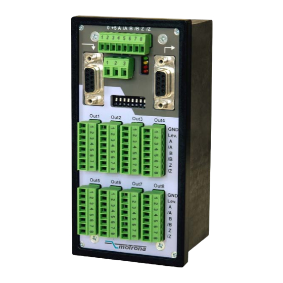
Figure: GV 460 and GV 480:
Splitters with 8 Output Channels
GV48002a_e.doc / Mrz-11
interface
GV 460 / GV 461
GV 480 / GV 481
Operating Instructions
motrona GmbH
Zwischen den Wegen 32
78239 Rielasingen - Germany
Tel. +49 (0)7731-9332-0
Fax +49 (0)7731-9332-30
info@motrona.com
www.motrona.com
Figure: GV 461 and GV 481:
Splitters with 4 Output Channels
Page 1 / 14
Advertisement
Table of Contents

Related Manuals for CONNECTRIC Motrona GV 460

Summary of Contents for CONNECTRIC Motrona GV 460
- Page 1 motrona GmbH Zwischen den Wegen 32 78239 Rielasingen - Germany Tel. +49 (0)7731-9332-0 Fax +49 (0)7731-9332-30 control – motion – interface info@motrona.com www.motrona.com GV 460 / GV 461 Impulse Splitters for Incremental Encoders with Potential Separation between Input and Outputs GV 480 / GV 481 Impulse Splitters for Incremental Encoders with all-around Potential Separation of all Circuits...
- Page 2 Safety Instructions • This manual is an essential part of the unit and contains important hints about function, correct handling and commissioning. Non-observance can result in damage to the unit or the machine, or even in injury to persons using the equipment ! •...
-
Page 3: Table Of Contents
Table of Contents Introduction and Block Diagram Electrical Connections and LED Function 2.1. Power Supply and LEDs 2.2. Auxiliary Encoder Supply 2.3. Impulse Inputs 2.3.1. Encoders with differential output (valid for output levels TTL/ 5 volts and for HTL / 10-30 volts as well) 2.3.2. - Page 4 GV48002a_e.doc / Mrz-11 Page 4 / 14...
-
Page 5: Introduction And Block Diagram
1. Introduction and Block Diagram GV460, GV461, GV480 and GV481 represent a series of incremental encoder splitters with a most compact, space-saving design and with most versatile technical features. All models are fully identical except for the number of output channels (4 or 8 channels) and the system of potential separation. - Page 6 +5,5V GNDIN +Lev. +VCC +VCC = 5,5 V Sel=Lo CASC in Sel=Hi +Lev. +VCC Stab Select Power CASC out Block Diagram GV 460 and GV 461 GV48002a_e.doc / Mrz-11 Page 6 / 14...
- Page 7 +5,5V GNDIN GNDO1 VCCO1 +Lev. Sel=Lo CASC in Sel=Hi GNDO2 VCCO2 +Lev. Stab Select Power CASC out Block Diagram GV 480 and GV 481 GV48002a_e.doc / Mrz-11 Page 7 / 14...
-
Page 8: Electrical Connections And Led Function
2. Electrical Connections and LED Function 2.1. Power Supply and LEDs The unit provides a 3-position screw terminal strip for supply from a 10 – 30 volts DC power unit. The current consumption is approx. 40 mA (no-load operation). The “Select” input terminal provides selection of the desired source encoder. Details will be described later. -
Page 9: Impulse Inputs
2.3. Impulse Inputs The 8-position DIL switch on the front side provides setting of the desired signal formats and levels. These settings are separately for each of the channels A / B / Z (see block diagram). For simplification, a short form of the four most common applications is shown below, with the encoder supply omitted: 2.3.1. -
Page 10: Differential Signals For Encoder Channels A And B, But Single-Ended Marker Pulse From Proximity Switch Or Photocell
2.3.4. Differential signals for encoder channels A and B, but single-ended marker pulse from proximity switch or photocell Besides the most common standard configurations shown before, the unit allows setting of any other input configuration (e.g. differential encoder inputs on channels A, /A, B, /B, but single- ended index signal on input Z (from a proximity switch, photocell or similar) The block diagram shows which of the DIL switch positions is responsible for each of the channels. -
Page 11: The Outputs
2.4. The Outputs All outputs provide the non-inverted and the inverted signals at any time, even when on the input side the inverted signals are not available. The potential situation between the outputs and other circuits is clearly explained by the block diagrams in chapter 1. - Page 12 Cascaded units allow selection of the active source encoder via the encoder select input on the 3-position power connector (see also block diagram): LOW (or open): outputs refer to the encoder input of the same unit HIGH (10 – 30 volts): outputs refer to the encoder input of the preceding unit It is possible at any time to switch over from one to the other source encoder during operation.
-
Page 13: Technical Specifications
3. Technical Specifications Power supply 10 – 30 VDC Power consumption: ca. 40 mA (without encoder supply) Aux. encoder supply *) built-in 5.5 V, 200 mA (short-circuit proof) Max. frequency TTL (differential) and RS422: 500 kHz (diff. voltage >0,5V) HTL (10 - 30 V): 200 kHz Input level with HTL single-ended Low: <... -
Page 14: Dimensions
4. Dimensions 60,5 mm (2.382'') 70,0 mm (2.756'') 72 mm (2.835'') 8 mm (0.315'') GV48002a_e.doc / Mrz-11 Page 14 / 14...
Need help?
Do you have a question about the Motrona GV 460 and is the answer not in the manual?
Questions and answers