Advertisement
Quick Links
Advertisement

Related Manuals for inVue Plunger Lock III

Summary of Contents for inVue Plunger Lock III
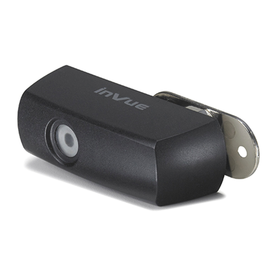
- Page 1 Plunger Lock III PL203...
- Page 2 It may be necessary to remove cabinet doors to allow for screw access and lock attachment. Application Plunger Lock III is designed for glass sliding panel doors with an existing hole ranging from 22 mm – 32 mm (0.87” – 0.26”). Reference Cabinet Requirements on pages 4 and 5.
-
Page 3: Cabinet Requirements
CABINET REQUIREMENTS CABINET REQUIREMENTS X = Plunger Length = 23.5 mm (0.91”) Y = Panel Thickness & Panel Gap must be 20.5 mm (0.81”) or less Z = Panel Thickness: 5.8 mm – 10 mm (0.23” – 0.4”) 3 mm (0.12”) Plunger Lock TOP VIEW Hole Diameter 22 mm –... - Page 4 Determine if front panel is on right or left hand side. Optional. The lock is sized to fit a 22 mm – 23 mm hole. Note: The illustrations in this booklet are for right To install lock into larger hole (24 mm - 32 mm) use the front panel orientation.
- Page 5 Slide Plunger Lock through hole in front panel. Rotate back plate until holes on back plate align and seat with screw holes on Plunger Lock. Back Plate...
- Page 6 Using screws provided, alternate tightening screws to Close cabinets before testing lock operation. ensure proper fit. Note: #1 Phillips screwdriver with magnetic tip recommended.
- Page 7 LOCK STATUS INDICATORS Position IR2 Key against lock, push button and wait for “beep” before removing key. Lock and unlock product several times to ensure proper operation. Unlocked IR2 Key must be charged and activated. See IR2 Key instruction guide. Hold until you get a confirmation “beep.”...
- Page 9 Corporate Office (North America) // 704.752.6513 • 888.55.INVUE Europe, Middle East & Africa // +31.23.8900150 Asia Pacific // +852.3127.6811 Latin America // +52.55.9000.3957 © 2012 InVue Security Products Inc. All rights reserved. InVue is a registered trademark of InVue Security Products.
Need help?
Do you have a question about the Plunger Lock III and is the answer not in the manual?
Questions and answers