
Related Manuals for sielco EXC GX Series


Summary of Contents for sielco EXC GX Series
- Page 1 FM super-compact transmitter series User and maintenance manual Version 1.0 – 01/2019 SIELCO Headquarter: Via Toscana, 57/59 - 20090 - Buccinasco (MI) Tel. +39-02-45713300 Fax +39-02-45713351 e-mail: info@sielco.org www.sielco.org...
- Page 2 User Manual Page 2 of 71...
- Page 3 We used the utmost care in making a complete manual with detailed, precise, and updated information; however, the contents herein cannot be regarded as binding towards our company. SIELCO, in their constant commitment to improve the quality of their products, reserve the right to vary the device’s technical features without prior notice. For updates, please visit our web-site www.sielco.org...
-
Page 4: Table Of Contents
Summary ........................6 NTRODUCTION 2 USED SYMBOLS ........................7 ! ........................8 AFETY FIRST Symbols used ..........................8 Warnings ............................8 Warning instruction ........................11 ..................12 IELCO PRODUCTS AND ADDED VALUE Full conformity to EC regulations ....................12 Quality in series manufacturing ....................12 Overdesigning for performance .................... - Page 5 12 RFB-GX AMPLIFIER’S SERIES ..................61 12.1 Configuration of the equipment ....................61 12.2 Connecting amplifier and transmitter through the RS485 port ............ 63 12.3 Impostazioni indirizzi porta RS485 ....................64 13 M ............65 AINTENANCE SOFTWARE UPGRADE AND WARRANTY 13.1 Maintenance ..........................
-
Page 6: Introduction
EC anti-magnetic noise requirements. In addition, this device complies with EC 2014/30/EU (low voltage), 2014/53/EU (RED), 2014/35/EU (EMC) standards. And that’s not all: Sielco products provide greater value added and incomparable quality. For further details, refer to Chap. 4. ... -
Page 7: Used Symbols
USED SYMBOLS CONSULT DOCUMENTATION ALTERNATING VOLTAGE MAINS SWITCH ON MAINS SWITCH OFF DANGER, HIGH RF VOLTAGE HAZARD As for 2012/19/EU requirements this equipment cannot be discharged in the environment at its end of life but must be given to the appropriate collection centers which will provide for recycling User Manual Page 7 of 71... -
Page 8: Safety First
This manual describes in detail the menus that appear on the LCD display: as the software is continually updated, some of the screens shown in the chapters below may be different than those that appear on your device. In case of doubt, contact Sielco. - Page 9 • Upon loss of the protective-ground connection, all accessible conductive parts (including parts that may appear to be insulating) can render an electric shock. • To avoid explosion, do not operate this equipment in an explosive atmosphere. • To avoid personal injury, do not remove covers or panels. Do not operate the system without the covers and panels properly installed.
- Page 10 3.2.d Emergency resuscitation technique Step 1 Check the victim for responsiveness. If there is no response, immediately call for medical assistance, and then return to the person. Step 2 Position the person flat on their back. Kneel by their side and place one hand on the forehead and the other under the chin.
-
Page 11: Warning Instruction
If it is really necessary, and after authorization of Sielco srl, very qualified technical staff only can work on or with live parts. In this special case special safety precautions must be taken. Sielco srl declines any responsibility if any safety rule is not respected. The replacement of the accessible fuse must be made with the transmitters turned off and using a fuse with the identical characteristics only as specified by the manufacturer. -
Page 12: Sielco Products And Added Value
Choosing a product merely because it costs less than another one doesn’t make sense if its performance costs are high. For this reason, Sielco has undertaken to ensure that its products provide maximum return on the investment made in purchasing them. In particular, the EXC-RFBxxGX series transmitters are distinguished by the following features: •... -
Page 13: Identifying Your Model
D E N T I FY I N G Y O UR M OD E L The EXC(RFB)xxGX Series family of transmitters/amplifiers has characteristics common to all of the models (for example, the command menu, the primary controls, the primary connection inputs, etc.). However, the range of models is in continual evolution, and each model is distinguished by a different transmission power and by characteristics specific to the series, or by optional characteristics that make it unique. -
Page 14: Equipment Description , Commands And Inputs
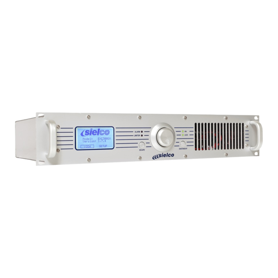
QU I P M E N T E S C R I P T I ON OM M AN D S AN D I N P UT S The primary commands and connections for the EXC(RFB)xxGT Series are common to all the models. However, each version has been created with a different unit rack and may be equipped with different functions and connections. - Page 15 6.1.b EXC100-300GX Transmitters Front • Dimensions (LxHxD): 483 x 88 x 395 mm • Weight: 8 kg • Output connector: N Rear User Manual Page 15 of 71...
- Page 16 6.1.c EXC(RFB)500÷1600GX Transmitters and Amplifiers Front • Dimensions (LxHxD): 483 x 88 x 585 mm • Weight: 12 kg • Output connector: 7/16” • Notes: these models internally differ for the type and/or number of output transistors/ RF power modules and/or the power supply Rear 15 16 17...
- Page 17 6.1.d EXC(RFB)2000GX Transmitter and Amplifier Front • Dimensions (LxHxD): 483 x 133 x 585 mm • Weight: 21 kg • Output connector: 7/16” Rear 15 16 User Manual Page 17 of 71...
- Page 18 6.1.e EXC(RFB)3000-5000GX Transmitters and Amplifiers Front 6.1.f • Dimensions (LxHxD): 483 x 177 x 650 mm • Weight: 30-33 kg • Output connector: 7/8” • Notes: these models internally differ for the type and/or number of the RF pallets / power supply modules. E.g.: EXC3000GX (4/2), EXC3500GX (4/3), EXC5000GX (6/3).
-
Page 19: List Of Commands And Inputs
List of commands and inputs The commands and inputs that, according to your model, may be available on the device are listed below: Control panel 1 and 1A – allows the user to set device functions, and to view and set operating parameters. It is composed of the following: •... - Page 20 Power socket or cable – used to connect to a mains supply. Ground – used to ground the device, to ensure safe operation. Predisposition remote control antenna – input for an external GSM antenna (to be connected if the device is equipped with a remote control option via the cellular phone network) (OPTIONAL).
-
Page 21: Installation
Should doubts or technical problems arise during the installation procedure, it is strongly recommended that you contact SIELCO or a local agent/dealer. • Should technical problems or doubts of any kind arise during installation, SIELCO would be happy to provide qualified technical assistance. Technical intervention by personnel not authorized by SIELCO should not be performed. •... -
Page 22: Wiring The Device
• In such cases, it is advisable, if not indispensable, to install a protector, an insulating transformer, or possibly an electromechanical mains voltage regulator. Upon request, SIELCO can provide all of these accessories. • Even though the mains regulator allows for a wide incoming voltage range, it is important to avoid operating using high impedance mains lines in proximity to the lowest permitted AC limit: if the line falls below a given value while fully loaded, the control circuit for the lowest AC limit may trigger a very dangerous oscillating on/off cycle. - Page 23 The MPX connector is internally connected in parallel to the RIGHT connector. As such, if the MPX connector is in use, the simultaneous connection of signals to the LEFT and RIGHT connectors is not possible. Again in this case, the highest impedance position is 5 kOhm.
- Page 24 EXC(RFB)3000GX-3500GX-5000GX 3-phase 400Vac with neutral 3-phase 230Vac without neutral Single phase 230Vac Before connecting the power, ensure that it is appropriate and is able to support the consumption required by the transmitter model you intend to use. The power supplied by the mains input must satisfy the requirements outlined in section 7.3.c. ...
- Page 25 7.4.e Parallel port for remote control (optional) Where necessary, connections can be made to the REMOTE parallel port [19]. Various lines are located in this port for simple, direct control of the transmitter via a male DB9 connector. Connection of the pins is outlined in the following table: Connection Notes 1, 5, and...
-
Page 26: Audio Operating Modes And Associated Lf Connections
U D I O OP E R AT I N G M OD E S AN D AS S OC I AT E D C ON NE C T I O N S This section describes how to select the various available operating modes, and how to make audio connections according to your requirements. -
Page 27: Connection Of The Aes/Ebu Digital Audio Input (Optional)
The MPX connector is internally connected in parallel to the RIGHT connector. As such, if the MPX connector is in use, the simultaneous connection of signals to the LEFT and RIGHT connectors is not possible. In such case, the highest impedance position is 5 kOhm. - Page 28 8.6.b SEXC25DAC Digital Audio interface board characteristic The SEXC25DAC board is a simple yet very high-quality Digital Audio Input Interface board which decodes the serially encoded digital audio stream into a balanced stereo signal which is sent to the balanced input of the transmitters. It simply replaces the original passive input board (SEXC25IN) at the inner side of the rear panel and is able to manage the standard analogue audio signal or the digital audio.
-
Page 29: Connection To Mpx Input
Connection to MPX input The MPX input permits to use an externally created stereo multiplex signal as modulation input. This may came from an external Stereo encoder or a Radio Link. If the length of the cable delivering the signal to the MPX connector is only a few meters long, a 50 Ohm (RG58) cable can be used. -
Page 30: Operating With The Rds And Sca Encoders
Operating with the RDS and SCA encoders In addition to the aforementioned operating modes, this device is able to transmit an auxiliary signal (RDS or SCA) connected to the rear AUX terminal as follows: Connect the AUX terminal [16] to the RDS or SCA encoder output. If the internal stereo encoder is used, connect the MODULATION MONITOR output [15] to the “driver tone”... - Page 31 For further details please consult the proper User Manual of this board which is actually the same provided with the externally mounted RDS19 RDS Generator. User Manual Page 31 of 71...
-
Page 32: Operating With Remote Control With Ethernet/Gsm Adapter Board (Optional)
Through a GSM device, either PC + modem or cellular. Control may be extensively done through a client software running on PC/laptops or by SMS in a simplified way. SIELCO provides this client software running on Windows OS. The Ethernet/GSM adapter board provides an internal link with the transmitter CPU in order to continuously update data to and from remote controllers on nearly all functioning, preset or status parameters. -
Page 33: Menu And Navigation Commands
E N U AN D N AV I G AT I ON C OM M AN D S To view the device’s operating parameters, and to set parameters according to your requirements, you will need to navigate the commands menu shown on the LCD display. You can navigate the menu using: •... -
Page 34: Navigating The Commands Menu
Navigating the commands menu Generally, you can navigate the commands menu as follows: From the main screen (which appears when you turn the device on), turn the knob until one of the two main menus, VIEW or SETUP, are highlighted. In the example that follows, SETUP is highlighted. Briefly press the knob to access the highlighted menu. - Page 35 and the previous page by selecting PREV. PAGE. 9.4.b EDIT, ABORT, and ESCAPE Once you’ve entered one of the sub-menus in the SETUP menu, turning the knob allows you to select three commands that appear at the bottom of the screen: •...
-
Page 36: Asic Operations
10 B AS I C OP E R AT I ON S Immediately following installation, the first time the device is turned on, it is absolutely fundamental that the instructions outlined in this chapter be followed. Failure to perform the adjustments and controls explained in this section could cause serious damage to the device or interference with other broadcasters or services that operate via radio;... - Page 37 Transmitter display Amplifier display 10.1.a Operating frequency (not available on amplifiers) Ensure that the FREQUENCY sub-menu is selected; otherwise, turn the knob to select it. Press the knob to access the sub-menu. The following screen will appear ( section 11.3.a): Ensure that the EDIT option is selected;...
- Page 38 If the device is currently in operation (green ON LED lit up), the Pow. out: indicator will show the power currently supplied. Otherwise, with the device on stand-by (yellow ON LED lit up), the indicator will remain at 0.0W. 10.1.c Modulation sensitivity (not available on amplifiers) Turn the knob until the MPX SENS.
- Page 39 10.1.e Transmission modes (mono/stereo) and pre-emphasis (not available on amplifiers) Turn the knob until the MODE sub-menu is selected, then press the knob to confirm. The transmission mode settings screen will appear ( section 11.3.f): Ensure that the EDIT option is selected; otherwise, turn the knob to select it, then press to confirm. A value will be indicated after Mode.
-
Page 40: Changing From Stand-By To Full Operation
The year will be indicated. Turn the knob to set the current year, then press to confirm. OK will be highlighted. Three choices are now available: • If the parameters set are correct – skip directly to step 53) to confirm the settings. •... -
Page 41: Changing From Full Operation To Stand-By And Vice-Versa
If the red ALARM indicator light appears, this means that an alarm event has occurred. When this happens, check the type of alarm on the display, refer to the error table in section , and resolve the problem. While in normal operation, we recommend that you leave your device on the STATUS sub-menu, found under the main VIEW menu ( ... -
Page 42: Enus Description
11 M E N U S D E S C RI P T I ON 11.1 Default screen As soon as the device is turned on, the default screen will appear on the display, indicating the following information: • Model: indicates the transmitter model (in this example, EXC30GT). •... - Page 43 During normal use of the device, we recommend that the STATUS menu be selected. Each of the above sub-menus is used to view parameters; as such, options cannot be selected using the knob, with the exception of the MPX GRAPH and VIEW LOG sub-menus. Refer to 11.2.d and 0. STATUS sub-menu 11.2.a The screen for this sub-menu contains the following items:...
- Page 44 In the example above, the Right channel is indicated. Adjustments can be made to the nominal modulation level via the SETUP menu ( 11.3). AUX sub-menu 11.2.c (not available on amplifiers) The screen for this sub-menu shows the modulation level for the Aux RDS/SCA signal: The above example shows the standard level of the RDS signal (2 KHz), as well as the bar indicator, which shows the level graphically.
- Page 45 • Frequency: indicates the operating frequency (in the example, 98.00 MHz). • Mode: indicates Mono, Stereo, Mono L+R, or Mpx mode (in the example, Stereo). • Preemphasis: indicates the modulation preemphasis value (in the example, 50 microseconds). • Elapsed hours: indicates the time elapsed since the device was first turned on in the factory (in the example, 1 hour). ...
-
Page 46: Setup Menu
VIEW LOG sub-menu 11.2.h This sub-menu provides a historical record of events (transmitter turned on, turned off, on stand-by, etc.) and alarms (insufficient modulation, excessive reflected power, etc.) that took place during operation. The transmitter’s memory (non-volatile) can record up to 100 alarms/events. - Page 47 SETUP Page 3 Transmitter display Amplifier display SETUP Page 4 Transmitter display To move from one page to another, select the commands NEXT PAGE or PREV PAGE using the knob, then press to confirm. As you can see, the three pages allow you to access the following settings: •...
- Page 48 Use of this menu is described in section 10.1.a. 11.3.b POWER setting Used to adjust the transmitter’s output power. The display shows the following: • Pow. set – set power • Pow. out – measurement of the power supplied Use of this menu is described in section 10.1.b. 11.3.c MPX SENS setting (not available on amplifiers) Used to adjust modulation input sensitivity according to the low frequency level available.
- Page 49 Using the knob, select OK to save the settings, EDIT to make further changes, or ABORT to exit without saving the new settings, then press to confirm (for further details regarding these commands, see 9.4a). 11.3.e LIMITER setting (not avaible on amplifier) Used to limit the peak modulation at a maximum value.
- Page 50 11.3.g DISPLAY setting Used to optimize display legibility, based on ambient lighting conditions and the angle of the visual field. This screen shows: • Backlight – followed by the current backlighting value (in the example, 3) • Contrast – followed by the current contrast value (in the example, 4) To change these parameters: Ensure that the EDIT option is selected;...
- Page 51 setting 11.3.i SET OUT (remote control output) This screen allows you to define the logic levels (high/low) used for remote control: You can define whether the status of the following lines normally has a HIGH or LOW logic level: • OnAIR logic –...
- Page 52 Ethernet setup menu IP setup on Ethernet sub-menu 11.3.l PASSWORD (menu protection) setting Used to activate and set the passwords to protect access to the menus. Two passwords are available: • LEV 1 – this level is more restrictive and protects access to both the VIEW and the SETUP main menus. On the display of the equipment the following screen appears without any other information Whenever VIEW or SETUP menu is selected, the equipment will ask for a suitable password •...
- Page 53 LEVEL 1 PASSWORD To protect both main menus, activate/set the LEV 1 password as follows: Select SET PASSWORD LEV 1 with the knob, then press to confirm. The following screen will appear: Using the knob, select EDIT and press to confirm. OFF (password deactivated) will be selected. Turn the knob to select ON, then press to confirm.
- Page 54 • UNLOCK – an alarm is issued when the internal PLL frequency synthesizer is unlocked. • MPX – an alarm is issued when low (or no) modulation is detected for a given period of time. In general, to set alarms: Turn the knob to select the alarm that you wish to activate/configure (e.g., LOW RF POW), then press to confirm.
- Page 55 UNLOCK (not available on amplifiers) From this screen, a time can be set, beyond which an alarm will be issued if the transmitter’s internal synthesizer continues to be unlocked. In the above example, if the synthesizer is unlocked for a Delay of 31 seconds, an alarm will be issued. To set the synthesizer unlock alarm: Ensure that the EDIT option is selected;...
- Page 56 • NO – the alarm history will not be deleted (in cases of accidental access to the sub-menu, where there is no actual need to delete the history). After either command is selected, the display will return to the SET ALARM sub-menu. ...
-
Page 57: Hidden Or Factory Menus (Under Level 3 Password)
11.3.o PW TIMER setting Used to automatically decrease the transmitter’s power by a given percentage during a specific time period (e.g., night time). The display shows the following parameters: • OFF or ON – power reduction deactivated (OFF) or activated (ON). •... -
Page 58: Output Power Reduction By Remote Input Parallel Connector
IMPORTANT! Always note down the level 3 password and backup it in a safe place. Should you loose it, the total re- programming of the equipment or the CPU replacement at SIELCO will be mandatory, with the related costs which this operation involves. - Page 59 11.5.a How to enable Output power reduction by the remote-control line Select the “SETUP” tree on the default page of the equipment menu, Descend the submenu to “NEXT PAGE” and down to “SET IN” line on the new page Press the knob to enter ( section 10.3 of user manual) Press again the knob to confirm “EDIT”, than change “Type”...
- Page 60 The function of this submenu is not modified by the remotely controlled power reduction and for its function you may still refer to it proper section of the manual ( section 11.3 o of user manual): Briefly you must preset: “EDIT”...
-
Page 61: Rfb-Gx Amplifier's Series
12 RFB-GX AMPLIFIER’S SERIES RFBxxGX is a series of solid state MosFet based FM broadband amplifiers extremely compact and efficient which shares the same characteristics of the transmitters from which derives. In fact, they are essentially the same equipment from which the modulator, the input interface and the driver board were removed. - Page 62 The first two presets are the most used, making the equipment use essentially independent in their control but permitting the amplifiers to be driven by an external properly preset exciter through its RF input connector. In this case the parameters of each machine must be independently controlled by its menu ...
-
Page 63: Connecting Amplifier And Transmitter Through The Rs485 Port
12.2 Connecting amplifier and transmitter through the RS485 port As indicated in the previous section, remote-management of both the equipment can be performed through the RS485 serial bus. The RS485 interface port is an optional board (SEXC30RS485) which must be factory mounted. This is also the primary way to control when used within a transmitter TXxxGX by the system controller. -
Page 64: Impostazioni Indirizzi Porta Rs485
12.3 Impostazioni indirizzi porta RS485 In order to allow communication between the "Exciter“ and the "Master Amplifier" it is necessary to assign the correct addresses: the "Master Amplifier" needs to be assigned the address code 01 and the "Exciter" the code 02. The addresses of the two machines must be independently set through their menu. -
Page 65: Aintenance Software Upgrade And Warranty
Regularly remove dust from air filter and internally: (see 11.3.h). After a few years of continuous service, it is advisable to have the device overhauled in the factory or in a specialized Sielco appointed laboratory, where its characteristics can be checked against the initial parameters. If necessary, regular maintenance operations can also be carried out at this time. -
Page 66: Warranty
For details please refer to the dedicated booklet. 13.3 Warranty Like all Sielco solid-state equipment, this transmitter series carries a one-year warranty on all its components, with the exception of the final RF power module, which may be damaged by faulty output connectors. -
Page 67: Roubleshooting
14 T R OU B LE S H O OT I N G If all instructions set in this manual are followed, any equipment of the EXC(RFB)xxGX series will guarantee several years of continuous, perfect service. However, should problems arise, refer to this chapter before contacting the local authorized assistance point. - Page 68 14.1.c Over temperature The Over temperature alarm may be referred to a system over temperature (CPU Temp.) or only to a RF power stage over temperature (RF temp.); each of the said temperatures is taken via a specific heat probe. Before reaching the max allowed temperature, the alarm LED starts flashing, to signalize the approach to the limit condition.
-
Page 69: Ircuit Description
This section’s sole purpose is to provide general explanations about the device operation in order to simplify the maintenance by skilled personnel authorized by Sielco. As already mentioned, no internal adjustments are required for normal operation. Tampering with the internal settings renders the warranty null and void and could seriously damage the equipment, compromising the guaranteed performance. -
Page 70: Echnical Features
16 T E C H N I C AL FE AT U RE S Frequency range ................................87,5 ÷ 108 MHz FM modulation ............................. 75 kHz (adjustable) peak deviation Mono ................................... 180kF3E Stereo ................................. 256kF3E Audio/MPX input level ........................-3,5 ÷ +12,5 dBm @ 75 kHz deviation Audio input connectors ................................ -
Page 71: Ptionals
17 O P T I O N AL S Many different optional boards are available to increase versatility where needed, adding new features to basic transmitter. Here are the most common ones. SEXC30RS485 RS485 INTERFACE BOARD SEXC19DAC AES/EBU DIGITAL AUDIO INPUT BOARD SEXC25DAC AES/EBU DIGITAL AUDIO INPUT BOARD SEXC30REMC ETHERNET WEB-SERVER / SNMP SEXC30REMC+ ETHERNET WEB-SERVER / SNMP AND...
Need help?
Do you have a question about the EXC GX Series and is the answer not in the manual?
Questions and answers