Advertisement
Quick Links
Advertisement

Related Manuals for Intech Micro 2100-D

Summary of Contents for Intech Micro 2100-D
- Page 1 INTECH Micro 2100-D REV. 1.1 TECHNOLOGY & QUALITY Z985 Installation Guide. 14.04-1...
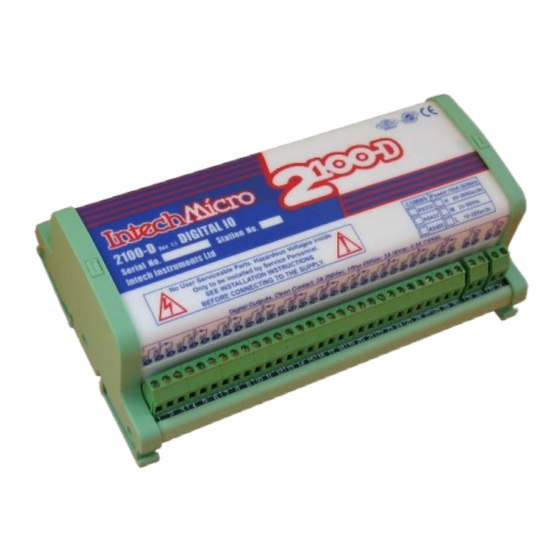
- Page 2 Section A: 2100-D Installation Guide Index. Section A. Description, Ordering and Specifications. Index. Page 2 Features and Ordering Information. Page 3 Specifications. Page 4 Terminals and layout. Page 5 Dimensions. Page 6 Section B: Jumpers and LED Functions Tables. S1 Function Settings.
-
Page 3: Ordering Information
2100-DI-X 12 Digital Inputs: RS485 COMMS, 85~264Vac/dc Power Supply. 2100-DO-X 12 Digital Outputs: RS485 COMMS, 85~264Vac/dc Power Supply. 2100-D 85~264Vac/dc Note: The 2100-D is factory set to RS485. The 2100-D-X is field selectable for RS422 or RS485, and H or M power supply. Ordering Examples. 1/ 2100-D-422-M 2100-D;... - Page 4 Warning: These products are not designed for use in, and should not be used for patient connected applications. In any critical installation an independant fail-safe back-up system must always be implemented. CAUTION: Dangerous voltages may be present. The 2100-D has no user serviceable parts. Protective enclosure only to be opened by qualified personnel. Remove ALL power sources before removing protective cover.
- Page 5 Only adjust jumpers with power OFF. Notes; 1. The 2100-D has 12 Digital Inputs and 12 Relay Outputs. 2. The 2100-DI has 12 Digital Inputs. The 12 Relay Outputs are not fitted. 3. The 2100-DO has 12 Relay Outputs. The 12 Digital Inputs are not fitted.
- Page 6 Remove ALL power sources before removing protective cover. * For ALL programming tables. Jumper Status: 0=JUMPER NOT INSERTED 1=JUMPER INSERTED. * Refer to ‘2100-D Terminals and Layout’ for the location of the following jumpers . 2100-D S1 Function Dip Switch Settings Note 1.
- Page 7 Note 4. All cables must be screened, with screen earthed at one end only. Refer ‘The Proper Installation & 24Vdc Wiring of the 2100-D.’ Note 5. 4K7 resistor not required for most types of 3 wire PNP transducers. Reed Switch or Relay contact.
- Page 8 IN-2000-AI, IN-2000-AO, IN-2000-DI, IN-2000-DO, FP21, IMPORTANT: SR25, etc. Use a 2100-4S to interface an RS485 Data Hi-way to an To other INTECH MICRO Remote (i) All cables must be existing RS422 Data Hi-way Stations & Shimaden Controllers etc.
-
Page 9: Installation
Series Remote Station.’ Communication Protocols. Protocol is available from Intech Instruments in ‘WORD’ format, free of charge. 2100-D protocol is the protocol used by Microscan to access data in stations. Use EX DI, EX DO, RCn messages to access station data. 14.04-9... - Page 10 Select ’Program Address’. (Located in ‘Station Programming Panel’, at the bottom right of the window. Enter the 2100-D serial number. (Written both on the 2100-D cover and the circuit board behind the power supply terminals. 80, 81 & 82. If the cover has been removed, the number on the circuit board is always correct.
- Page 11 Avoid mounting in cabinets with power control equipment. To maintain compliance with the EMC Directives the 2100-D is to be mounted in a fully enclosed steel fire cabinet. The cabinet must be properly earthed, with appropriate input / output entry points and cabling.
- Page 12 Refer to diagrams for connection details. Commissioning Check that all the above conditions have been met, and the wiring checked, before applying power to the 2100-D. Check each relay output functions correctly, and the relay specifications are not being exceeded.
Need help?
Do you have a question about the 2100-D and is the answer not in the manual?
Questions and answers