Table of Contents
Advertisement
Quick Links
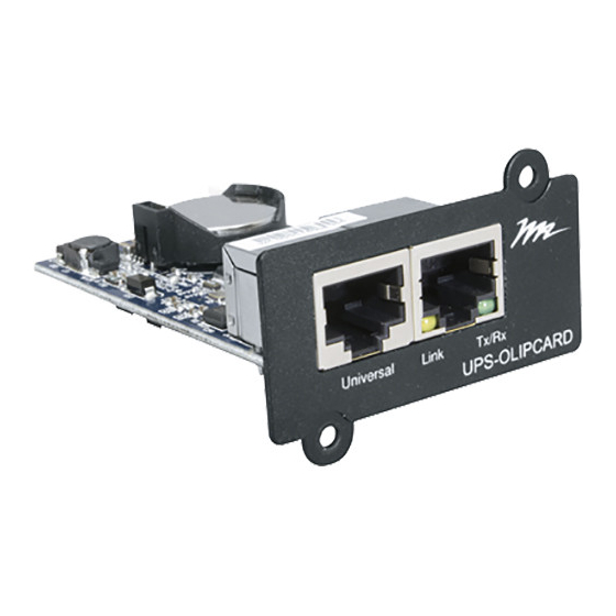
UPS Online Network Interface Card
THANK YOU
Thank you for purchasing a UPS Online Network Interface Card product. Please read these
instructions thoroughly before installing this product.
PRODUCT FEATURES
• Real-time UPS monitoring
• Remote Management System software provides management and configuration of the UPS via
web browser
• Auto-shutdown to protect servers and workstations from data loss due to power failure
User Manual
UPS-OLIPCARD
I-00784
Rev A
Advertisement
Table of Contents

Related Manuals for Middle Atlantic Products UPS-OLIPCARD


Summary of Contents for Middle Atlantic Products UPS-OLIPCARD
- Page 1 User Manual UPS Online Network Interface Card UPS-OLIPCARD THANK YOU Thank you for purchasing a UPS Online Network Interface Card product. Please read these instructions thoroughly before installing this product. PRODUCT FEATURES • Real-time UPS monitoring • Remote Management System software provides management and configuration of the UPS via web browser •...
-
Page 2: Table Of Contents
TABLE OF CONTENTS IMPORTANT SAFETY INSTRUCTIONS ....................5 INTRODUCTION ..........................9 Key Features ............................. 9 SYSTEM REQUIREMENTS ....................... 10 APPLICATION ............................ 10 UNPACKING ............................10 INSTALLATION ..........................11 Hardware Installation ........................11 Definitions for LED Indicators ...................... 11 Configuring the IP Address ......................12 Method 1: Using the Middle Atlantic Power Device Network Utility Tool ........ - Page 3 TABLE OF CONTENTS Setting EnergyWise Configurations ....................35 Viewing the EnergyWise Node List ....................36 CONFIGURING LOGS AND MAINTENANCE SETTINGS ..............39 Viewing Event Logs ......................... 39 Viewing Status Records ........................40 Configuring Data Log Graphing ....................... 40 Configuring Syslog Settings ......................42 Adding Syslog Servers.........................
- Page 4 APPENDIX A: IP ADDRESS SETTINGS FOR UPS-OLIPCARD ............92 Locating the Subnet on Your UPS-OLIPCARD ................92 Selecting an IP Address for Your UPS-OLIPCARD ................. 92 APPENDIX B: HOW TO CONFIGURE A UPS-OLIPCARD USER ACCOUNT ON AUTHENTICATION SERVERS ............................94 WARRANTY ............................95...
-
Page 5: Important Safety Instructions
IMPORTANT SAFETY INSTRUCTIONS This manual contains important instructions. Please read and follow all instructions carefully during installation and operation of the unit. Read this manual thoroughly before attempting to unpack, install, or operate the UPS. CAUTION! The UPS must be connected to a grounded AC CAUTION! Do not use an improper size power cord as it may power outlet with fuse or circuit breaker protection. - Page 6 IMPORTANT SAFETY INSTRUCTIONS Waste Electrical and Electronic Equipment (WEEE) Directive Correct disposal of this product: This symbol indicates that this product must not be disposed of with household waste, according to the WEEE Directive (2012/19/EU) and your national law. This product should be taken to a collection center licensed for the recycling of waste electrical and electronic equipment (EEE).
- Page 7 CONSIGNES DE SÉCURITÉ IMPORTANTES Ce manuel contient des instructions importantes. S'il vous plaît lire et suivre attentivement toutes les instructions lors de l'installation et le fonctionnement de l'unité. Lisez attentivement ce manuel avant de déballer, installer ou utiliser l'onduleur. ATTENTION! L'onduleur doit être connecté à une prise ATTENTION! NE PAS UTILISER POUR DES APPAREILS DE MÉDICAL OU SOUTIEN DE LA VIE! En aucun cas, cet d'alimentation secteur à...
- Page 8 CONSIGNES DE SÉCURITÉ IMPORTANTES Directive sur les déchets d'équipements électriques et électroniques (WEEE) Elimination correcte de ce produit: Ce symbole indique que ce produit ne doit pas être éliminé avec les ordures ménagères, conformément à la directive WEEE (2012/19/EU) et à votre législation nationale. Ce produit doit être déposé...
-
Page 9: Introduction
INTRODUCTION The Middle Atlantic Online Network Interface Card (UPS-OLIPCARD or just OLIPCARD) allows for remote monitoring and control of a UPS attached to a network. After you install the hardware and configure an IP address, you can access, monitor, and control your UPS from anywhere in the world. -
Page 10: System Requirements
SYSTEM REQUIREMENTS • Windows® 7 32/64-bit or later with .Net 4.0 Framework or later • A computer with a Windows or Linux Operating System (for optional Power Manager Client) • An Ethernet connection to an existing network • NMS (Network Management Station) compliant with SNMP (for optional NMS management) APPLICATION UNPACKING Inspect the Network Management Card upon receipt. -
Page 11: Installation
4. Connect an Ethernet cable from your network into the Ethernet port of the Middle Atlantic UPS- OLIPCARD. NOTE: The Middle Atlantic UPS-OLIPCARD is hot-swappable, so you do not need to turn off the UPS to install it. Definitions for LED Indicators... -
Page 12: Configuring The Ip Address
2. After installation is complete, run the “Middle Atlantic UPS-IPCARD Setup Utility” program from All Programs > Middle Atlantic UPS-IPCARD Setup Utility. The main dialog of the “Middle Atlantic Products UPS-IPCARD Setup Utility” program is shown as follows. 3. The configuration tool will display all Middle Atlantic network cards of present on the same network. - Page 13 INSTALLATION 5. Click Tools > Device Setup or double click the OLIPCARD you want to configure. 6. You can modify the IP Address, Subnet Mask, and Gateway address for the Device MAC Address listed in the Device Network Settings window, as follows. The factory default IP Address is 192.168.20.177, the default Subnet Mask is 255.255.255.0.
-
Page 14: Method 2: Using A Command Prompt
Press Enter. c. If replies are received, your computer can communicate with the IP address. For more information about selecting an IP address for your OLIPCARD, see “Appendix A: IP Address Settings for UPS-OLIPCARD” on page 92. Page 14... -
Page 15: Logging Into The Ups Remote Management System
LOGGING INTO THE UPS REMOTE MANAGEMENT SYSTEM The UPS Remote Management system is a browser-based interface to your OLIPCARD. With your IP address configured, enter it into a web browser in order to log into the system. To log into the UPS Remote Management system: 1. -
Page 16: Ups Summary
UPS SUMMARY The UPS summary screen provides a dashboard that includes information for current conditions, UPS status, system data, and recent events. To view UPS summary information: 1. Log into the UPS Remote Management System. For more information, see “Logging into the UPS Remote Management System” on page 15. 2. - Page 17 UPS SUMMARY • Location: UPS location (editable field) • Contact: Primary contact (editable field) • Uptime: Time since last power on 6. The Recent Device Events section of the screen displays the following: • Recent Device Events: Provides the date and time of the event along with an event description.
-
Page 18: Configuring Ups Settings
CONFIGURING UPS SETTINGS UPS menus include configuration interfaces for Status, Information, Configuration, Control, Outlet Control, Diagnostics, and Schedule. The following topics cover the interfaces in more detail. Viewing the UPS Status Screen To view the UPS status screen: 1. Log into the UPS Remote Management System. For more information, see “Logging into the UPS Remote Management System”... -
Page 19: Viewing The Ups Information Screen
CONFIGURING UPS SETTINGS • Status: Displays the present status of the output power the UPS is supplying to connected equipment. • Voltage: Output voltage of the UPS • Frequency: Output frequency • Load: Load expressed as a percentage of maximum load •... - Page 20 CONFIGURING UPS SETTINGS 2. Click UPS > Information. 3. The Information screen displays the following: • Model Name: The model name of the UPS • Voltage Rating: The nominal operating voltage rating • Working Frequency: The frequency of the UPS input/output power •...
-
Page 21: Setting Ups Configurations
CONFIGURING UPS SETTINGS • Extended Battery Pack: The amount of external battery packs connected to the UPS • Installation Place: Click the Find it button to sound an alarm and flash the LED indicators in order to identify your specific UPS when installed among others. Setting UPS Configurations To set the UPS configurations: 1. - Page 22 CONFIGURING UPS SETTINGS 3. In the Supplied Power field, select the desired output voltage provided to connected equipment. 4. Enter Utility Power Failure Condition settings as follows: a. High/Low Input (or Output) Voltage Threshold: When the utility input or output voltage exceeds this configured the threshold, the UPS will supply battery power to the connected equipment.
- Page 23 CONFIGURING UPS SETTINGS • Check Volt/Freq: If the utility voltage is in the range configured in the High/Low Bypass Voltage and the utility frequency is in the range configured in Frequency Tolerance, the UPS will enter Bypass mode. Otherwise the UPS will stop supplying output power.
- Page 24 CONFIGURING UPS SETTINGS b. External Battery Pack: Set the amount of external battery packs. This allows for an accurate runtime estimate based upon the total number of batteries. c. Periodical Battery Test: Set an interval of every 1, 2, 3, or 4 weeks to have the system perform a reoccurring battery test, if desired.
-
Page 25: Configuring The Ups Master Switch
CONFIGURING UPS SETTINGS b. Turn Off Delay: When supplying battery power, the UPS powers off this NCL outlet after the specified delay time is met. c. Turn On Delay: When the utility power restores, the UPS restores the output of this NCL outlet after the delay time is met. -
Page 26: The Ups Bank (Outlet) Control Screen
CONFIGURING UPS SETTINGS • If selecting Turn UPS Off (Standby Mode) to put the UPS into standby mode, configure the following settings: a. Shutdown Delay: How long the UPS waits before it turns off in response to a Standby Mode •... -
Page 27: Renaming Outlets
CONFIGURING UPS SETTINGS Choose ON to turn the outlets on immediately. Choose OFF to turn the outlets off immediately. 5. Click Apply. NOTE: Click Reset to clear any values selected on the screen. Renaming Outlets To rename outlets: 1. Log into the UPS Remote Management System. For more information, see “Logging into the UPS Remote Management System”... -
Page 28: Performing Ups Diagnostics
CONFIGURING UPS SETTINGS The Device Name Configuration screen appears. 4. Enter the desired name in the Device Name field. 5. Click Apply. NOTE: Click Reset to clear any values selected on the screen. Performing UPS Diagnostics The Diagnostics screen provides Battery Tests and Runtime Calibrations. These functions help you verify if the UPS can supply adequate battery runtime for the connected computers to shutdown properly. -
Page 29: Performing A Runtime Calibration
• LAST TEST DATE: Shows the date of the last test performed. Performing a Runtime Calibration NOTE: • Frequent calibration will shorten the life of your batteries. Middle Atlantic Products recommends one or two calibrations per year. • All outlets must be on in order to perform this function. -
Page 30: Resolving Battery Test Failures
CONFIGURING UPS SETTINGS 2. Click UPS > Diagnostics. The runtime calibration synchronizes the runtime estimate with the current load and battery capacity. When a runtime calibration initiates, the “Calibration is Initiated” event occurs. A runtime calibration will discharge the batteries completely. The batteries will be recharged automatically following a calibration. - Page 31 CONFIGURING UPS SETTINGS 2. Click UPS > Schedule. 3. The Shutdown section of the screen shows standby schedules in waiting and provide details for Name, Status, Shutdown Time, Restore Time, Frequency, and Bank. 4. In the Add New Shutdown Schedule section of the screen, choose from Once, Daily, or Weekly as follows: •...
-
Page 32: Configuring Wake On Lan (Wol) Features
CONFIGURING UPS SETTINGS The Add New Shutdown Schedule screen appears. 6. Enter values for the following fields: • Use the Active check box to Enable or Disable the shutdown. • In the Name field, enter the desired name of the schedule. •... - Page 33 CONFIGURING UPS SETTINGS The WoL Features screen appears. 3. In the Wake Conditions section of the screen make the following settings: a. Select the UPS Turn On check box to allow the registered network device to turn on the UPS during a power event. b.
-
Page 34: Configuring Wake On Lan (Wol) Lists
CONFIGURING UPS SETTINGS Configuring Wake on Lan (WoL) Lists To configure wake on LAN lists: 1. Log into the UPS Remote Management System. For more information, see “Logging into the UPS Remote Management System” on page 15. 2. Click UPS > Wake on Lan > Features. The WoL Lists screen appears. -
Page 35: Setting Energywise Configurations
CONFIGURING UPS SETTINGS 4. Select the Enabled check box to activate the receiver. 5. In the IP Address field, enter the desired IP address. 6. Click Apply. NOTE: Click Reset to clear any values selected on the screen. Setting EnergyWise Configurations To set EnergyWise configurations: 1. -
Page 36: Viewing The Energywise Node List
CONFIGURING UPS SETTINGS NOTE: This domain name must be the same as the one used on the Cisco switch. The field is limited to 31 characters. 6. Select Off-State Cache to add the endpoint into the cache of EnergyWise’s switch list after a reboot. - Page 37 CONFIGURING UPS SETTINGS 3. The following Parent and Children nodes appear: • UPS_Base: This parent node represents the OLIPCARD. A wattage reading is passed to your CISCO EnergyWise indicating the OLIPCARD’s power consumption. • UPS: This child node represents the UPS. A wattage reading is passed to your CISCO EnergyWise indicating the whole UPS’s power consumption.
- Page 38 CONFIGURING UPS SETTINGS • Keywords: This field is used for further describing the outlet. The field is limited to 31 characters. • Importance: This field is a value between 1 and 100 to indicate the outlet’s importance as high or low, respectively. Page 38...
-
Page 39: Configuring Logs And Maintenance Settings
CONFIGURING LOGS AND MAINTENANCE SETTINGS Logs menus include configuration interfaces for Event Logs, Status Logs, and Maintenance. The following topics cover the interfaces in more detail. Viewing Event Logs To view event logs: 1. Log into the UPS Remote Management System. For more information, see “Logging into the UPS Remote Management System”... -
Page 40: Viewing Status Records
CONFIGURING LOGS AND MAINTENANCE SETTINGS Viewing Status Records The status records display a list of records along with a date and time stamp. To view status records: 1. Log into the UPS Remote Management System. For more information, see “Logging into the UPS Remote Management System” on page 15. 2. - Page 41 CONFIGURING LOGS AND MAINTENANCE SETTINGS 2. Click Log > Graphing. 3. In the Graph Period section of the screen, configure the range of desired data by selecting one of the following options: • Select the Last radio button to choose an amount of days from the drop-down. •...
-
Page 42: Configuring Syslog Settings
CONFIGURING LOGS AND MAINTENANCE SETTINGS The graph appears on the lower part of the screen. NOTE: • Click Reset to clear any values selected on the screen. • Click Launch Graph in New Window to display the graph in a separate window instead of the lower part of the screen. - Page 43 CONFIGURING LOGS AND MAINTENANCE SETTINGS 2. Click Log > Syslog. 3. Click Add Server. The Syslog Server screen appears. 4. Enter a Server IP address of the Syslog server as desired. 5. Enter a Server Port value for the UDP port of the Syslog server. 6.
-
Page 44: Testing Syslog Servers
CONFIGURING LOGS AND MAINTENANCE SETTINGS Testing Syslog Servers To test a syslog server: 1. Log into the UPS Remote Management System. For more information, see “Logging into the UPS Remote Management System” on page 15. 2. Click Log > Syslog. 3. -
Page 45: Enabling Syslog
CONFIGURING LOGS AND MAINTENANCE SETTINGS 4. Make changes as desired. 5. Click Apply. NOTE: • Click Reset to clear any values selected on the screen. • Click Delete to remove the selected Syslog server. Enabling Syslog To enable syslog: 1. Log into the UPS Remote Management System. For more information, see “Logging into the UPS Remote Management System”... - Page 46 CONFIGURING LOGS AND MAINTENANCE SETTINGS 3. Select the Enabled check box to turn on Syslogs for the servers you configured. 4. In the Facility Code drop-down, select which program type is being used to log the message. 5. Click Apply. NOTE: Click Reset to clear any values selected on the screen.
-
Page 47: Configuring Event And Status Log Maintenance
CONFIGURING LOGS AND MAINTENANCE SETTINGS Configuring Event and Status Log Maintenance To configure event and status log maintenance: 1. Log into the UPS Remote Management System. For more information, see “Logging into the UPS Remote Management System” on page 15. 2. - Page 48 CONFIGURING LOGS AND MAINTENANCE SETTINGS c. Click Save next to the Save Status Records label to store existing status records into a text file. 5. Click Apply. NOTE: • Click Reset to clear any values selected on the screen. • Old event log and status record data is automatically deleted when there is no space available to record.
-
Page 49: Configuring System Settings
CONFIGURING SYSTEM SETTINGS System menus include configuration interfaces for a General, Security, Network Service, Notification, Reset/Reboot, and About. The following topics cover these sections in more detail. Configuring General Settings General settings include configurations for Time, Identification, and Daylight Saving Time. The following topics cover the interfaces in more detail. -
Page 50: Configuring Identification Values
CONFIGURING SYSTEM SETTINGS • Next NTP Update: The remaining time before next automatic update (if NTP selected) 6. In the System Time Configuration section of the screen, make the following settings: a. Select the Time Zone as desired. b. Select the Date Format as desired. c. -
Page 51: Configuring Daylight Saving Time
CONFIGURING SYSTEM SETTINGS 3. Configure the following Identification settings: • In the Name field, enter a familiar name for your OLIPCARD. • In the Location field, enter the location of your UPS. • In the Contact field, name who to contact for service or help. NOTE: Fields are limited to 15 characters 4. -
Page 52: Configuring Security Settings
RADIUS server. If the RADIUS server fails to respond, the system then uses the username and password configured in the Local Account. For more information, see “Appendix B: How to Configure a UPS-OLIPCARD User Account on Authentication Servers” on page 94. Page 52... -
Page 53: Configuring Local Accounts
Local Account. For more information, see “Appendix B: How to Configure a UPS-OLIPCARD User Account on Authentication Servers” on page 94. • LDAP Only: Select to have the user login to the OLIPCARD with a user name and password that is only authenticated with the LDAP server. -
Page 54: Configuring Remote Authentication Dial-In User Service (Radius) Servers
• The guest account has read-only access. • Only one user session at a time is permitted. • If you do not logout of the Remote Manager, the UPS-OLIPCARD will not allow a new session until the previous session times out. - Page 55 CONFIGURING SYSTEM SETTINGS 2. Click System > Security > RADIUS Configuration. 3. Click Add Server. The RADIUS Server Configuration screen appears. 4. In the Server IP field, enter a server IP address as desired. 5. In the Shared Secret field, enter the shared secret for your RADIUS server. 6.
-
Page 56: Configuring Lightweight Directory Access Protocol (Ldap) Servers
CONFIGURING SYSTEM SETTINGS • Select Test Setting if you wish to test the configuration. a. Enter a User Name. b. Enter a Password. • Select Skip Test if you don’t wish to test the configuration. 8. Click Apply. NOTE: Click Reset to clear any values selected on the screen. Configuring Lightweight Directory Access Protocol (LDAP) Servers To configure LDAP servers: 1. - Page 57 CONFIGURING SYSTEM SETTINGS The LDAP Server Configuration screen appears. 4. In the LDAP Server field, enter the IP address of your LDAP server. 5. Select the LDAP SSL check box to communicate with the LDAP server by LDAPS. 6. In the Port field, enter the TCP port used by the LDAP server. NOTE: The default Port value is 389.
-
Page 58: Configuring The Session Control Timeout
CONFIGURING SYSTEM SETTINGS NOTE: Click Reset to clear any values selected on the screen. Configuring the Session Control Timeout To configure the session control timeout: 1. Log into the UPS Remote Management System. For more information, see “Logging into the UPS Remote Management System” on page 15. 2. - Page 59 CONFIGURING SYSTEM SETTINGS 2. Click System > Network Service > TCP/IPv4. 3. In the Current Configuration section of the screen, view the following: • IP Address • Subnet Mask • Gateway • DNS Server 3. In the DHCP section of the screen, configure the following: a.
-
Page 60: Configuring Tcp/Ipv6 Settings
CONFIGURING SYSTEM SETTINGS 5. Click Apply. NOTE: Click Reset to clear any values selected on the screen. Configuring TCP/IPv6 Settings To configure TCP/IPv6 settings: 1. Log into the UPS Remote Management System. For more information, see “Logging into the UPS Remote Management System” on page 15. 2. -
Page 61: Configuring Snmpv1 Service Settings
CONFIGURING SYSTEM SETTINGS 5. In the Manual IPv6 Address section of the screen, enter the following: • Enter a System IP Address as desired. NOTE: The IPv6 configuration must also be Enabled and the Manual check box selected in order to enable the System IP Address field. 6. - Page 62 CONFIGURING SYSTEM SETTINGS b. IP/Host Name: The IP address or IP address mask with access to the RMS. A specific IP address allows exact access to the RMS, while 255 may be used as a mask as follows: • 192.168.20.255: Allows access to the RMS only on the 192.168.20 segment •...
- Page 63 CONFIGURING SYSTEM SETTINGS The Edit SNMPv1 Community screen appears. 4. In the Community field, modify the name as desired. 5. In the IP Address field, enter the IP address for the user. This is the IP address or IP address mask with access to the RMS.
-
Page 64: Configuring Snmpv3 Service Settings
CONFIGURING SYSTEM SETTINGS Configuring SNMPv3 Service Settings To configure SNMPv3 service settings: 1. Log into the UPS Remote Management System. For more information, see “Logging into the UPS Remote Management System” on page 15. 2. Click System > Network Service > SNMPv3 Service. 3. - Page 65 CONFIGURING SYSTEM SETTINGS d. Authentication Protocol: The authetnication protocol selected for the SNMPv3 user. e. Privacy Protocol: The privacy protocol selected for the SNMPv3 user. Enabling and Editing an SNMPv3 User To enable and edit an SNMPv3 user: 1. Log into the UPS Remote Management System. For more information, see “Logging into the UPS Remote Management System”...
-
Page 66: Configuring The Web Service
CONFIGURING SYSTEM SETTINGS 4. Use the Enabled check box to enable or disable the user. 5. In the User Name field, modify the user name as desired. NOTE: The user name must be 1 to 31 characters. 6. In the Authentication Password field, enter the password used to generate your authentication key for the SNMPv3 user. - Page 67 CONFIGURING SYSTEM SETTINGS 2. Click System > Web Service. 3. In the Access section of the screen, select one of the following: • Enabled HTTP: Enables the HTTP service. • Enabled HTTPS: Enables HTTPS service supporting the following encryption algorithms: o AES (256/128 bits) o Camellia (256/128 bits) o 3DES (168 bits)
-
Page 68: Configuring The Console Service
CONFIGURING SYSTEM SETTINGS 7. Click Upload Certificate to provide or replace the current certificate. NOTE: The certificate must be in a standard Privacy Enhanced Mail (PEM) format. 8. Click Apply. NOTE: Click Reset to clear any values selected on the screen. Configuring the Console Service To configure the console service: 1. -
Page 69: Configuring Ftp Services
CONFIGURING SYSTEM SETTINGS NOTE: The default is 23. You may enhance security and change the port to any unused number from 5000 to 32768, if desired. 5. In the SSH Settings section of the screen, enter a TCP/IP port number in the SSH Port field. NOTE: The default is 22. -
Page 70: Configuring Notification Settings
CONFIGURING SYSTEM SETTINGS 4. In the Service port field, enter the TCP/IP port of the FTP server. The default is 21. 5. Click Apply. NOTE: Click Reset to clear any values selected on the screen. Configuring Notification Settings Notification settings include configurations for Event Action, SMTP Server, E-mail Recipients, Trap Receivers, Short Message Service (SMS), and SMS Recipients. - Page 71 CONFIGURING SYSTEM SETTINGS 3. Click any of the Device or System Events links to show corresponding events on the lower part of the screen. 4. Click a desired event link. The Event Action screen appears. 5. Modify the corresponding response as follows: •...
-
Page 72: Configuring Smtp Server Settings
CONFIGURING SYSTEM SETTINGS • Send Email: Sends an email to a specific e-mail address (requires an accessible SMTP server) • Post Trap: A SNMP trap is sent to a specific IP address • Syslog: • Send SMS: When selected, sends a short message to a specified mobile phone number NOTE: An available SMS service provider is needed. -
Page 73: Configuring Email Recipients
CONFIGURING SYSTEM SETTINGS 3. Configure the following SMTP Server settings: a. In the SMTP Server Address field, enter the IP or host name of the SMTP server used to notify users via email. b. In the Sender E-mail Address field, enter the value to be used as the From field shown in e-mail messages sent to users. - Page 74 CONFIGURING SYSTEM SETTINGS 2. Click System > Notification > Email Recipients. 3. Click New Recipient. The Add New Email Recipient screen appears. 4. Select the Enabled check box. 5. Enter the desired email address. 6. Click Apply. NOTE: • Click Reset to clear any values selected on the screen. Page 74...
-
Page 75: Configuring Trap Receivers
CONFIGURING SYSTEM SETTINGS • Modify or delete an existing recipient by clicking the email addresss of the recipient from the list shown. The Configure Email Recipient screen appears where additional changes can be made. • Click the Test button from the E-mail Recipients screen to test a recipient’s account. Configuring Trap Receivers NOTE: You can configure up to 10 SNMP trap receivers. - Page 76 CONFIGURING SYSTEM SETTINGS The Add New Trap Receiver screen appears. 4. Select the Enabled check box. 5. In the Name field, enter a name for your trap receiver. 6. In the IP Address field, enter an IP address for your trap receiver. 7.
-
Page 77: Configuring The Short Message Service (Sms)
CONFIGURING SYSTEM SETTINGS Configuring the Short Message Service (SMS) SMS is a communication service used by mobile communication systems, using standardized communication protocols allowing the interchange of short text messages between mobile devices. For more information, see “Configuring Event Action Responses” on page 70. To configure the SMS: 1. - Page 78 CONFIGURING SYSTEM SETTINGS a. In the URL field, enter the URL of the SMS provider. NOTE: The following example variables may be used in the URL field when using an SMS service such as Clickatell. The variable values are retrieved by the SMS provider when sending messages: •...
- Page 79 CONFIGURING SYSTEM SETTINGS expressions will be replaced by relevant content before the Client sends a notification to SMS provider. • If you select Using HTTP Post, provide the following information: a. In the URL field, enter the URL of the SMS provider. b.
- Page 80 CONFIGURING SYSTEM SETTINGS This specification from an SMS provider is required before using the HTTP POST method to deliver messages to SMS providers.Select the Using HTTP POST option at the SMS Method field.Insert E_PHONE_NUMBER as recipient's mobile phone number and E_MESSAGE as the event message content described in the specification,and fill in the URL and POST BODY fields.The expressions will be replaced by the relevant content before the Agent/Client sends a notification to the SMS provider.
-
Page 81: Configuring The Sms Recipients
CONFIGURING SYSTEM SETTINGS This specification from a SMS provider is required before using the E-mail to deliver the messages to SMS providers.Select the Using E-mail option at the Service Provider field.Insert E_PHONE_NUMBER as recipient's mobile phone number and the E_MESSAGE as event message content described in the specification.Fill in the Address, Subject and Content fields.The expressions will be replaced with the relevant content before the Agent/Client sends a notification to the SMS provider. - Page 82 CONFIGURING SYSTEM SETTINGS 3. Click New Recipient. The Add New SMS Recipient screen appears. 4. Select the Enabled check box. 5. In the Recipient Name field, enter the name of the recipient. 6. In the Mobile Number field, enter the mobile phone number. NOTE: Enter the 10-digit number with no parenthesis, dashes, or spaces.
-
Page 83: Configuring Reset/Reboot Settings
CONFIGURING SYSTEM SETTINGS • Click Reset to clear any values selected on the screen. • Modify or delete an existing recipient by clicking the row of the desired recipient from the list shown. The Configure SMS Recipient screen appears where additional changes can be made. •... -
Page 84: Viewing About Information And Saving Or Restoring Configurations
CONFIGURING SYSTEM SETTINGS Viewing About Information and Saving or Restoring Configurations To view About information and save or restore configuration files: 1. Log into the UPS Remote Management System. For more information, see “Logging into the UPS Remote Management System” on page 15. 2. -
Page 85: Restoring Default Settings, Password Reset, And Firmware Upgrades
RESTORING DEFAULT SETTINGS, PASSWORD RESET, AND FIRMWARE UPGRADES Restoring Default Settings and Resetting Passwords To reset the Middle Atlantic UPS-OLIPCARD to its default setting (including WEB login user name and password): 1. Remove the two retaining screws on the card without turning off the UPS. -
Page 86: Performing A Firmware Upgrade
Performing a Firmware Upgrade To perform a firmware upgrade: 1. Ensure that the UPS-OLIPCARD to be upgraded is correctly installed in the UPS and that the UPS is powered on. 2. Connect the UPS-OLIPCARD to the network and use the UPS-OLIPCARD Setup Utility to locate and identify the card to be upgraded. - Page 87 Open a command prompt. b. Type C: and press Enter. c. Type ftp xxx.xxx.xxx.xxx and press Enter. NOTE: The ‘xxx.xxx.xxx.xxx’ is the IP Address of the UPS-OLIPCARD to be updated. d. When prompted enter your username and password. NOTE: The default username and password is admin and admin, respectively.
- Page 88 NOTE: If put c:\map\mapsnmpdata_XXX.bin was not successful, type ftp –w:16384 xxx.xxx.xxx.xxx and repeat the step 6 sub-steps again. 7. Clear the current firmware version on your UPS-OLIPCARD by performing the following steps: a. Disconnect your UPS-OLIPCARD from the network. b. Remove your UPS-OLIPCARD from the UPS c.
-
Page 89: Confirming Firmware Updates
After updating your firmware, the system forces you to change the default password for security purposes. Confirming Firmware Updates To confirm an updated firmware version: 1. Open a browser and go to the IP Address of your UPS-OLIPCARD Page 89... - Page 90 RESTORING DEFAULT SETTINGS, PASSWORD RESET, AND FIRMWARE UPGRADES The current firmware version appears on the Login screen as follows: Page 90...
-
Page 91: Troubleshooting
IP If the green LED is off: address on the management card • Check if the UPS-OLIPCARD is properly seated in the device and the using method 1 or device power is turned on. method 2 in If the yellow LED is off : “Configuring the IP... -
Page 92: Appendix A: Ip Address Settings For Ups-Olipcard
In order to assign an IP address to the Middle Atlantic UPS-OLIPCARD, you must determine the range of the available IP addresses, and then choose an unused IP address to assign to the OLIPCARD. - Page 93 APPENDIX A: IP ADDRESS SETTINGS FOR UPS-OLIPCARD Similarly, if the Subnet Mask is 255.255.0.0, the IP Address for Network Management Card could be set up as 192.168.*.* to reach the same subnet as the computer. 2. Type ping 192.168.20.240 in the command prompt to see if that arbitrary address is being used.
-
Page 94: Appendix B: How To Configure A Ups-Olipcard User Account On Authentication Servers
APPENDIX B: HOW TO CONFIGURE A UPS-OLIPCARD USER ACCOUNT ON AUTHENTICATION SERVERS When you first access external authentication servers to log into the system, the default account settings are view or read only. To modify the account permissions, you need to set the RADIUS and LDAP attributes as explained in the following topics. -
Page 95: Warranty
Factory Distribution United States: New Jersey, California, Illinois - Canada: Ontario - The Netherlands: Weert At Middle Atlantic Products we are always listening. Your comments are welcome. Middle Atlantic Products is an ISO 9001 and ISO 14001 Registered Company. Page 95...